


The ICS TRIPLEX T8442C is a speed monitoring module for the Trusted TMR Triple Modular Redundancy safety system. It performs real-time monitoring of shaft speed and acceleration of rotating machinery, provides safety shutdown protection against overspeed and over-acceleration, and independently realizes turbine speed control and mechanical protection functions. Suitable for key equipment such as steam/gas turbines, pumps, compressors and generators, it features hardware fault tolerance, high-speed response, high isolation and comprehensive diagnostic capabilities. Certified by TÜV and compliant with IEC 61508 SIL 3 safety level, it serves as a core component for safety protection of critical industrial units.
Download
Core Architecture & Composition
1. Overall Architecture
Adopts a hybrid redundant architecture of TMR input + quadruple redundant output. A single module integrates 3 independent rotating machinery monitoring groups, each supporting one piece of rotating equipment; one module can accommodate up to 3 turbine trains. Each group is equipped with 3 TMR speed input channels and a 2-channel quadruple redundant fault-tolerant shutdown output structure, eliminating single-point failure risks.
2. Core Sub-components
- HIU Host Interface Unit: The core of system communication, control and processing, providing 2oo3 voting and SOE sequence of events recording. Equipped with 3 independent DSPs and ASICs for isolated fault operation without mutual interference.
- SFIU Speed Field Interface Unit: Implements TMR input and quadruple redundant output control, with 2500V pulse optoelectromagnetic isolation, integrated pulse detection and relay drive circuits.
- SFTU Speed Field Terminal Unit: Connects field devices to the module, completing power conversion, relay status monitoring, and current/voltage supervision.
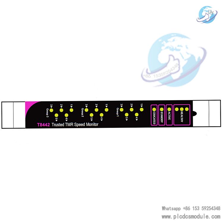
- FPU Front Panel Unit: LED status indication for visual display of module health, active/standby status and channel I/O status.
Supporting Terminal Components
- T8846 SIFTA: Speed input field terminal, compatible with active/passive speed probes, supporting signal conditioning for 9 TMR input channels.
- T8891 SOFTA: Speed output field terminal, providing 2-channel quadruple redundant safety relay output per group; 3 units configured per module.
- TC-801: Cable assembly for module-to-field terminal connection.
Core Functions
- Speed & Acceleration Monitoring: Real-time collection of shaft speed and acceleration; compatible with active/passive speed probes; resolution ±1RPM, accuracy up to 0.01% full scale.
- Safety Protection Shutdown: Triggers safety shutdown upon overspeed and over-acceleration threshold violation; adopts non-contact relay output with de-energized trip priority mode.
- Independent Control Capability: Functions as a self-contained fault-tolerant control subsystem; maintains independent protection logic execution even during processor or communication faults.
- Redundancy & Fault Tolerance: 2-out-of-3 (2oo3) input voting and quadruple redundant output; single-channel faults do not affect overall system operation with hardware-implemented HIFT fault tolerance.
- Diagnostics & Self-Testing: Comprehensive automatic diagnosis and on-board self-testing; covert fault detection with safe state transition; 1ms SOE event resolution.
- Hot Standby Redundancy: Supports Companion Slot hot standby configuration with seamless active/standby module switching and online module replacement.
- Safety Configuration Management: Prohibits protection threshold elevation during unit operation; critical parameters can only be modified at zero speed to safeguard safety boundaries.
Key Features
- 3 independent rotating machinery monitoring groups, supporting up to 3 devices per module
- 3 TMR speed input channels per group, compatible with active/passive probes
- 2-channel quadruple redundant non-contact shutdown control output per group
- 2500V pulse electromagnetic isolation, full electrical isolation for field I/O
- Onboard SOE sequence of events recording with 1ms resolution
- Hot standby redundancy, hardware fault tolerance and comprehensive self-diagnostics
- Front panel LED status indication for fast fault location
- TÜV certified, IEC 61508 SIL 3 safety compliance
- Configurable de-energized/energized trip modes for diverse load adaptation
Technical Specifications
- Speed Input Frequency: 0~30000Hz (active/passive probe compatible)
- Speed Measurement Resolution: ±1RPM
- Measurement Accuracy: 0.01% full scale or 1RPM (whichever is larger)
- System Power Supply: 20~32VDC, typical 24VDC; power consumption 22W
- Field Power Supply: Dual 24VDC, 18~32VDC
- Withstand Isolation Voltage: 2500V pulse withstand, electromagnetic isolation
- SOE Resolution: 1ms
- Operating Temperature: 0~+60℃
- Storage Temperature: -25~+70℃
- Dimensions: 266mm×30mm×303mm
- Weight: 1.28kg
- Safety Certification: IEC 61508 SIL 3 (TÜV Certified)
Application Scenarios
- Petrochemical Industry: Speed protection for turbine-driven compressor and pump units
- Power Industry: Overspeed protection for gas/steam turbines and generators
- Energy Sector: Safety monitoring of large-scale rotating machinery
- Metallurgy & Papermaking: Speed safety control for critical transmission equipment
FAQ
Q1: What is the difference between T8442C and T8442?A1: The T8442C is an enhanced upgraded version of the T8442 with full compatibility. It features optimized diagnostics, stability and environmental adaptability, with identical supporting terminals and wiring methods for direct replacement.
Q2: What is the maximum number of devices monitored per module?A2: Equipped with 3 independent monitoring groups, it can monitor up to 3 rotating machines with independently configurable thresholds and protection logic for each group.
Q3: What types of speed probes are supported?A3: Compatible with both active and passive speed probes via T8846 SIFTA connection. Active probes can be powered by the terminal without external power supply.
Q4: Relay type and trip modes of the output?A4: Each group adopts 2-channel quadruple redundant non-contact safety relays. Both de-energized trip (priority) and energized trip modes are configurable via software, corresponding to normally open/normally closed terminals of SOFTA.
Q5: What does SIL 3 certification mean?A5: Compliant with IEC 61508 SIL 3 with high safety integrity level. It is applicable to high-risk safety-critical applications and meets stringent protection requirements for turbines and other key equipment.
Q6: Is on-site module replacement supported?A6: Companion Slot hot standby is supported. With a standby module configured, faulty modules can be hot-swapped online with seamless active/standby switching without interrupting protection functions.
Q7: Relationship between rotational speed and gear tooth count?A7: Calculation formula: RPM = Frequency × 60 ÷ Number of gear teeth. Correct gear tooth count configuration is required for accurate speed calculation.
Q8: How to troubleshoot faults?A8: Check front panel LEDs first: Flashing red Healthy light indicates slice faults; flashing red input light indicates probe/circuit faults; abnormal output requires inspection of SOFTA and wiring, combined with IEC 61131 toolset fault codes for precise positioning.
Q9: Can it work independently without the main controller?A9: Yes. As an independent fault-tolerant subsystem, it can still execute overspeed/over-acceleration shutdown protection even if the main controller or communication fails.
Q10: What restrictions apply to configuration modification?A10: Critical parameters such as overspeed threshold, acceleration threshold and dead zone can only be modified at zero speed. Only safety-oriented parameter adjustments are allowed during operation to avoid misoperation risks.


 3005319639