BENDER IRDH275‑435 Insulation Monitoring Device
IRDH275‑435 BENDER ISOMETER® Series Insulation Monitor
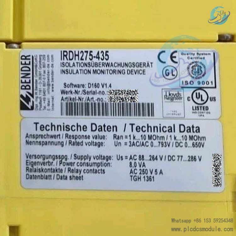
IRDH275‑435 is a digital insulation monitoring device (earth fault monitor) for unearthed (floating) IT AC and DC systems. Order code B 9106 5100, DIN rail mount. It continuously monitors the insulation resistance to earth of unearthed single-phase, three-phase AC and DC systems, detects earth faults in a timely manner to ensure continuous operation of IT systems, complying with North American NEC, CEC and IEC 61557‑8 standards.

Working Principle
The unit adopts patented AMPPlus (AMPPbus) measurement principle. It injects a measuring signal into the monitored system to measure insulation resistance to ground in real time. This principle can identify AC faults, DC faults and symmetrical insulation faults. For large earth leakage capacitance caused by inverters and rectifiers (max. 500μF supported), the device automatically adapts and compensates to eliminate measurement distortion brought by large distributed capacitance and guarantee measurement accuracy in complex power systems.
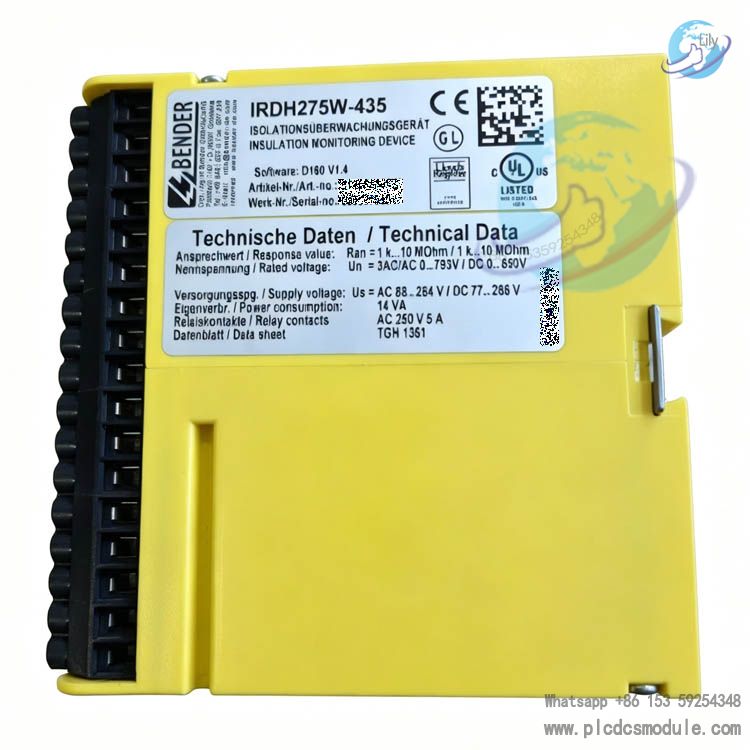
Compared with versions with suffix B, IRDH275‑435 features one-way ASCII output via RS‑485, isolated current output of 0‑400μA. It does not support bidirectional BMS communication and event history storage.
Main Technical Specifications
- Monitored system voltage: AC 0‑793V, DC 0‑650V; expandable to AC7200V / DC1760V with AGH series voltage coupler; frequency range DC~460Hz.
- Power supply: AC 88‑264V / DC77‑286V, power consumption ≤14VA; independent power supply for the unit, monitoring remains available even if the monitored system is de-energized.
- Insulation alarm threshold: Two independent adjustable response thresholds, adjustable from 1 kΩ~10 MΩ. Pre-alarm and main alarm can be configured separately.
1kΩ‑10kΩ: absolute error ±1kΩ; 10kΩ‑10MΩ: relative error ±10%. - Response performance: Response time<5s under condition of fault resistance equal to half of set threshold and leakage capacitance of 1μF. Hysteresis function is equipped to prevent frequent alarm chattering.
- Measurement circuit: Measuring peak voltage ±50V; measuring current ≤278 μA in case of fault short circuit, no interference to the monitored system.
- Relay output: 2-channel passive SPDT changeover contacts; contact rating AC250V/DC300V, switching capacity 5A. Supports energized (fail-safe) / de-energized (non-fail-safe) operation modes, factory default de-energized mode.
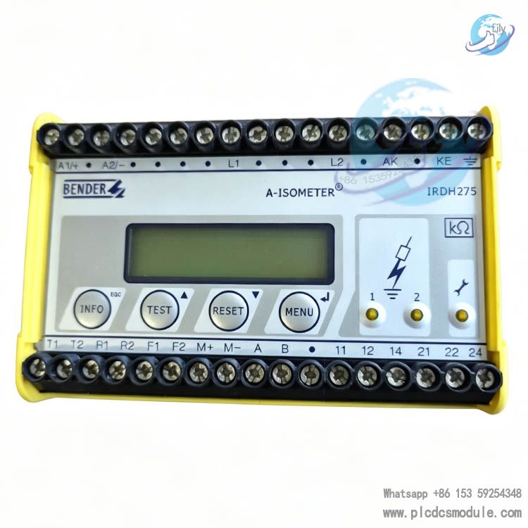
- Human-machine interface: Backlit 2-line LCD display showing real-time insulation resistance; front panel with INFO, TEST, RESET, MENU keys. INFO key for checking device parameters and system leakage capacitance; local / external button test and reset supported. RS‑485 one-way ASCII communication; isolated 0‑400μA analog output for connecting external meter to display insulation resistance.
- Self-monitoring: Continuous self-supervision of hardware and earth connection fault. Manual / automatic self-test available. System fault LED lights up and relay triggers alarm when internal device fault occurs.
- Environment & mounting: DIN rail mounting, M4 screw mounting optional. Operating temperature ‑10℃~+55℃; protection class IP30 for device body, IP20 for terminals.
Core Functions
- Dual-stage insulation fault alarm: When system insulation resistance to earth drops below set threshold, corresponding LED lights up and relay outputs switch signal, separating pre-alarm and main alarm. Fault latching supported, fault can be cleared by local or remote reset.
- System earth fault monitoring: Only L1 and L2 terminals connected to the monitored system are required to complete insulation monitoring of all phases for three-phase, single-phase and DC circuits, no need to connect all live conductors.
- Earth continuity monitoring: Continuously monitors protective earth wiring of the unit. Earth connection failure triggers system fault alarm directly to avoid monitoring failure.
- External expansion: Supports external test button and reset button; external analog indicator meter; AGH voltage coupler for high-voltage IT systems.
- Standby input for interlock: Standby input terminal. Measurement will be suspended when closed, used for interconnection of multiple insulation monitors to avoid mutual interference during simultaneous measurement.
Application Scenarios
Suitable for various unearthed IT power supply systems:
- Rectifier and variable frequency drive loads; UPS, battery DC systems;
- Medical equipment, industrial heating equipment, switching power supply systems;
- Marine, railway transit and industrial high-reliability power supply.
Note: When multiple IRDH275 monitors are interconnected via bus tie switch, only one insulation monitor can perform measurement at the same time, interlock via F1/F2 standby input terminals.
Key Differences between IRDH275‑435 and IRDH275B‑435
| Item | IRDH275‑435 (This model) | IRDH275B‑435 |
|---|---|---|
| RS‑485 | One-way ASCII data stream | Bidirectional BMS protocol, network interaction available |
| Analog output | 0‑400μA | 0 (4)‑20mA isolated output |
| Event storage | No | With RTC clock, stores 300 time-stamped event records |
| Interconnection control | Hardware interlock via external F1/F2 terminals | Automatic bus interconnection control via RS‑485 |
Accessories
- External display meter: 7204‑1421;
- High voltage coupler: AGH150W‑4 (DC high voltage), AGH204S‑4 (medium voltage AC), AGH520S (max. 7200V three-phase AC).
Supplement: IRDH375 series for panel embedded version.
BENDER IRDH275‑435 FAQ
Q1: Can IRDH275‑435 be used in TN earthed systems?
No. This device is designed only for IT unearthed (floating) AC and DC systems, not applicable for TN/TT earthed systems. Basic measuring voltage AC 0‑793V, DC 0‑650V; higher voltage coverage with AGH coupler.
Q2: For three-phase IT system, only L1 and L2 are connected without L3, can insulation of all three phases be monitored?
Yes. Based on AMPPlus measuring principle, connecting L1 and L2 terminals is sufficient to monitor insulation to earth of L1/L2/L3. For DC system, connect L1 to L+ and L2 to L‑; for single-phase system connect two live conductors.
Q3: Long system cables and heavy inverter loads bring high earth leakage capacitance, what will be the impact?
Maximum allowable system leakage capacitance is 500 μF, factory setting 150 μF. The unit automatically compensates capacitance, but higher capacitance leads to longer alarm response time. Measurement distortion occurs if capacitance exceeds 500 μF. System leakage capacitance value can be read via INFO key.
Q4: How to set two alarm thresholds Ran1 and Ran2 in engineering practice?
Both thresholds adjustable from 1 kΩ~10 MΩ independently. Common engineering setup: Ran1 as pre-alarm for insulation deterioration warning, Ran2 set at lower resistance for main fault alarm. Relays are passive SPDT changeover contacts, fail-safe / non-fail-safe mode selectable.
Q5: Can IRDH275‑435 still monitor insulation when the main monitored circuit is de-energized?
Yes. The unit has independent power terminals A1/A2. As long as the instrument is powered normally, insulation monitoring continues even if the monitored IT system is powered off.
Q6: What are the core differences between IRDH275‑435 and IRDH275B‑435?
IRDH275‑435: RS‑485 one-way ASCII output, analog output 0‑400μA, no event history recording and no bidirectional BMS communication. IRDH275B‑435: bidirectional BMS protocol RS‑485, 0/4‑20mA output, time-stamped event storage and automatic bus interconnection control.
Q7: Multiple IT sections connected by bus tie switch with multiple IRDH275‑435, how to avoid mutual interference?
When bus tie switch closes to parallel multiple IT systems, only one insulation monitor can be in measurement state at any time. Use F1/F2 standby control terminals, connect auxiliary contact of bus tie switch to F1/F2. Idle monitors enter standby mode and suspend measurement to prevent measurement conflict. IRDH275‑435 only supports hardware terminal interlock without automatic bus control.
Q8: What causes "System fault" alarm on the device?
System fault LED indicates internal device fault or external wiring abnormality. Common causes: ① KE protective earth terminal without reliable PE connection; ② Hardware self-test failure; ③ Broken L1/L2 monitoring wiring. Troubleshooting: Check KE earth connection and L1/L2 wiring, perform TEST self-test. Replace instrument if fault persists due to hardware damage.