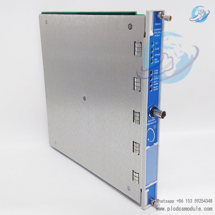
Note; All products on this site are special products, the market price has been fluctuating, the specific customer service offer shall prevail, because the product is a new product, the picture is not a real shot, please confirm with customer service before placing an order model and product, price and other details, the site used, new are for sale, please contact customer service communication. The Bently Nevada 3500/53 Electronic Overspeed Detection System is a core component of the 3500 Series Machinery Monitoring System, specially designed for overspeed protection scenarios. It features high reliability, fast response capability and redundant speed measurement functions, and strictly complies with the overspeed protection requirements specified in the American Petroleum Institute (API) Standards 670 and 612.
The system can be flexibly configured into a 2-out-of-2 voting architecture or the recommended 2-out-of-3 voting architecture, providing accurate and reliable overspeed monitoring and protection for all types of rotating machinery. It prevents safety incidents caused by overspeed during equipment operation, and is widely applied in industries reliant on large-scale rotating machinery, such as petroleum, chemical engineering and electric power. Its operation requires integration with a 3500 rack equipped with a redundant power supply, which further ensures the system’s stable operation under complex working conditions.
related documents
 BENTLY 3500/53.pdf

Core Technical Parameters
Input Parameters
Signal Specifications: Each overspeed detection module can receive a single sensor signal from a proximity probe sensor or a magnetoelectric sensor, with an input signal range of +10.0 V to -24.0 V. The module internally clamps signals beyond this range to prevent equipment damage.
Input Impedance: Fixed at 20 kΩ to ensure stability and accuracy of signal transmission.
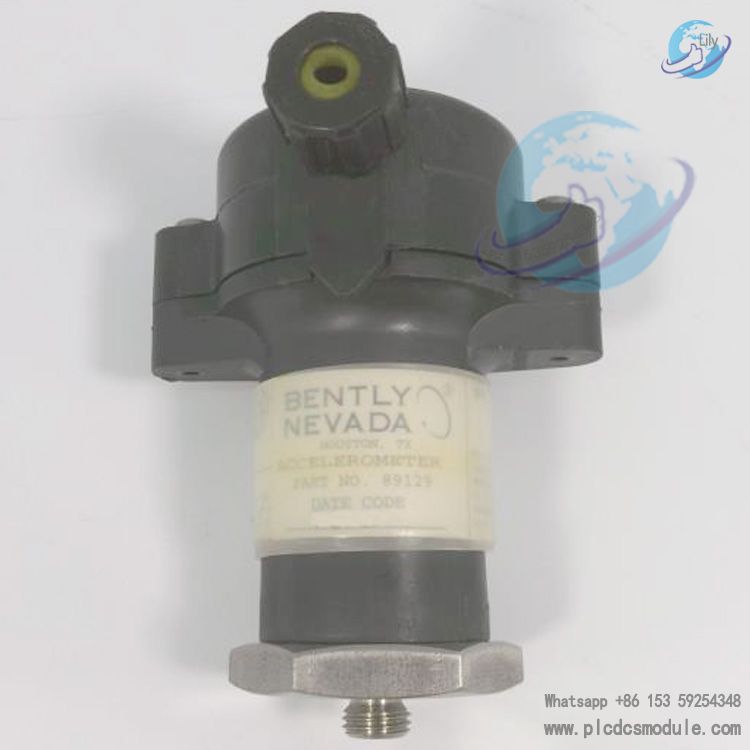
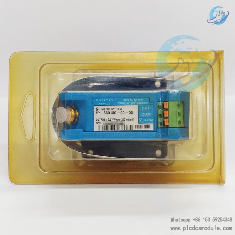
Compatible Sensors: It supports a wide range of Bently Nevada sensors, including 3300 8 mm proximity sensors, 3300 16 mm HTPS sensors, 7200 Series 5 mm, 8 mm, 11 mm and 14 mm proximity sensors, 3300 RAM proximity sensors, as well as magnetoelectric sensors, featuring broad adaptability.
Frequency Response and Speed Range: It supports 1 to 255 pulse events per revolution, with a maximum full-scale speed of 99,999 rpm and a maximum input frequency of 20 kHz. The minimum input frequency is 0.0167 Hz for proximity sensors (corresponding to 1 rpm at 1 event per revolution) and 3.3 Hz for passive magnetoelectric sensors.
Speed Accuracy: The accuracy is ±0.1 rpm when the speed is below 100 rpm; ±1 rpm when the speed ranges from 100 to 10,000 rpm; and ±0.01% when the speed ranges from 10,000 to 99,999 rpm, ensuring precise monitoring data across different speed intervals.
Output Parameters
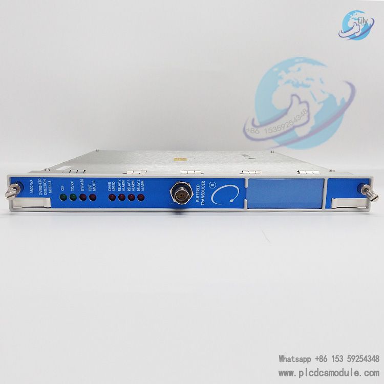
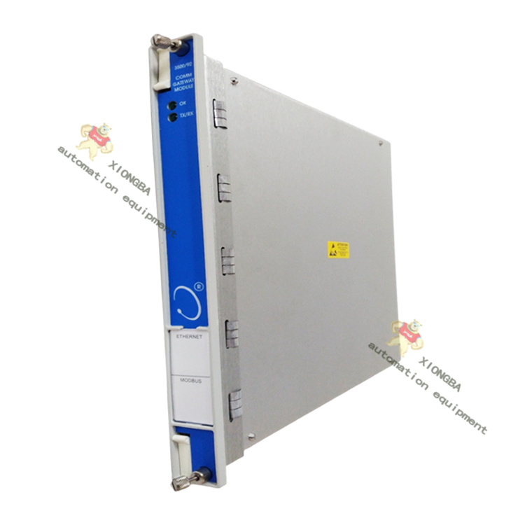
Front Panel LED Indicators: It includes an OK indicator (indicating normal module operation), a TX/XR indicator (indicating communication status between the module and other modules in the 3500 rack), a Bypass indicator (indicating the module is in bypass mode), a Test Mode indicator (indicating the module is in test mode), and an alarm indicator (indicating alarm status of related relays), providing intuitive feedback on module operating status.
Buffered Sensor Output: Each module is equipped with a coaxial connector on the front panel for buffered output. The connector has short-circuit protection and electrostatic discharge (ESD) protection functions, with an output impedance of 550 Ω.
Sensor Power Supply: It provides -24 Vdc DC power with a maximum output current of 40 mA, delivering stable power supply for compatible sensors.
Recorder Output: It outputs a +4 to +20 mA current signal proportional to the full-scale speed (rpm) of the module. A short circuit at the recorder output terminal will not affect the normal operation of the module. The voltage compatibility range is 0 to +12 Vdc (at the load terminal), and the load resistance range is 0 to 600 Ω.
Resolution: The resolution at room temperature is 0.3662 µA/bit with an error of ±0.25%. The error across the full temperature range is ±0.7%, and the update rate is approximately 100 ms, ensuring data real-time performance.
Relay Parameters
Type: It adopts single-pole double-throw (SPDT) relays with an epoxy-sealed design, providing excellent environmental sealing performance.
Arc Suppressor: A 250 Vrms arc suppressor is standard-equipped to extend the service life and enhance the stability of the relays.
Contact Ratings: The maximum switching power is 120 W for DC and 600 VA for AC. Under resistive load, the maximum switching current is 5 A, and the minimum switching current is 100 mA (at 5 Vdc). The maximum switching voltage is 30 Vdc for DC and 250 Vac for AC. The contact service life can reach 100,000 operations at 5 A, 24 Vdc or 120 Vac. Each relay can be switched between Normally De-energized and Normally Energized modes via a switch.
Signal Conditioning and Alarm Settings
Threshold Settings: The automatic threshold is applicable to any input signal above 0.0167 Hz (corresponding to 1 rpm at 1 event per revolution), with a minimum signal amplitude of 1 V peak-to-peak required for triggering. The manual threshold can be selected by the user within the range of +9.9 Vdc to -23.9 Vdc, with a minimum signal amplitude of 500 mV peak-to-peak required for triggering.
Alarm Settings: Alarm thresholds can be set based on speed. All alarm thresholds are configured via software and adjustable within the range of 0% to 100% of the full scale. The alarm delay is less than 30 ms when the frequency is above 300 Hz, enabling rapid response to potential risks.
Scaled Outputs: It includes two scaled values: Speed and Peak Speed. Speed is the core measured value of the channel and can be incorporated into the continuous registers of the communication gateway module; Peak Speed is for display only and does not provide alarm functions.
Environmental and Safety Compliance
Environmental Limits
- Operating Temperature: -30 °C to +65 °C (-22 °F to +149 °F), suitable for various temperature conditions in industrial sites.
- Storage Temperature: -40 °C to +85 °C (-40 °F to +185 °F), facilitating equipment transportation and storage.
- Humidity: 95% non-condensing humidity, allowing stable operation in humid environments.
Physical Characteristics
Dimensions and Weight
- Monitoring Module: Dimensions are 241.3 mm × 24.4 mm × 241.8 mm (9.50 in × 0.96 in × 9.52 in), with a weight of 0.82 kg (1.8 lb).
- I/O Module: Dimensions are 241.3 mm × 24.4 mm × 99.1 mm (9.50 in × 0.96 in × 3.90 in), with a weight of 0.45 kg (1.0 lb).
Rack Space Requirements
- Monitoring Module: Each channel occupies 1 full-height front slot.
- I/O Module: Each channel occupies 1 full-height rear slot.
Ordering and Compatibility Requirements
Compatibility Requirements
When adding the 3500/53 module to an existing 3500 system, ensure the system meets the following firmware and software version requirements (or later versions):
3500/20 module firmware Version G, 3500/01 software Version 2.00, 3500/02 software Version 2.03, 3500/03 software Version 1.13. In addition, the 3500 rack incorporating the overspeed detection system must be equipped with a redundant power supply.
Ordering Information
- Product Model: 3500/53-AXX-BXX. Hereinto, A denotes the channel option (02 = 2-channel system, 03 = 3-channel system); B denotes the agency certification option (00 = no certification, 01 = CSA/NRTL/C certification).
- Spare Parts List: Includes 3500/53 Overspeed Detection Module (Model 133388-01), Overspeed Detection I/O Module (Model 133396-01), Disposable ESD Wrist Strap (Model 04425545), IC Removal Tool (Model 04400037), Firmware IC (Model 134129-01), 4-position Green Internal Terminal Connector Plug (Model 00580438), 6-position Green Internal Terminal Connector Plug (Model 00580436), 10-position Green Internal Terminal Connector Plug (Model 00580432), and 3500/53 Overspeed Detection Manual (Model 134939-01).

Customers who purchased this product are also browsing the following products:
Bently Nevada 136719-01 Earthing I/O Module
Bently Nevada 165335-01 990 Vibration Transmitter
BENTLY NEVADA 135462-01 Solar Turbines-specific board
Bently 132419-01 2201 MONITORING SYSTEM FOUR CHANNEL MONITOR


 3005319639