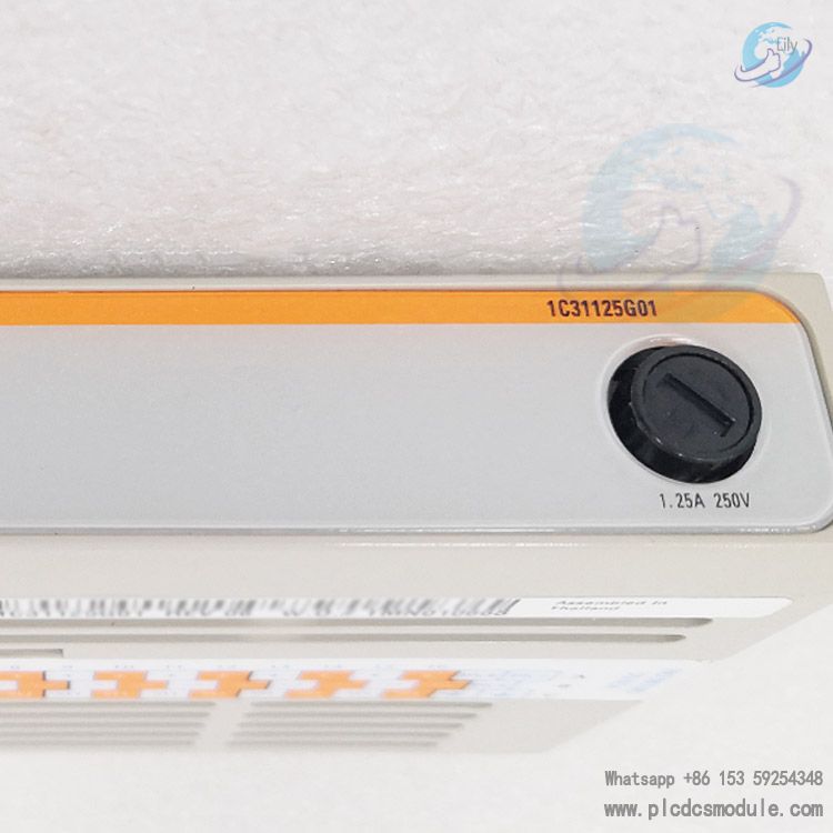
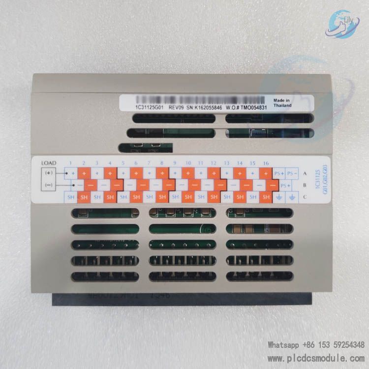
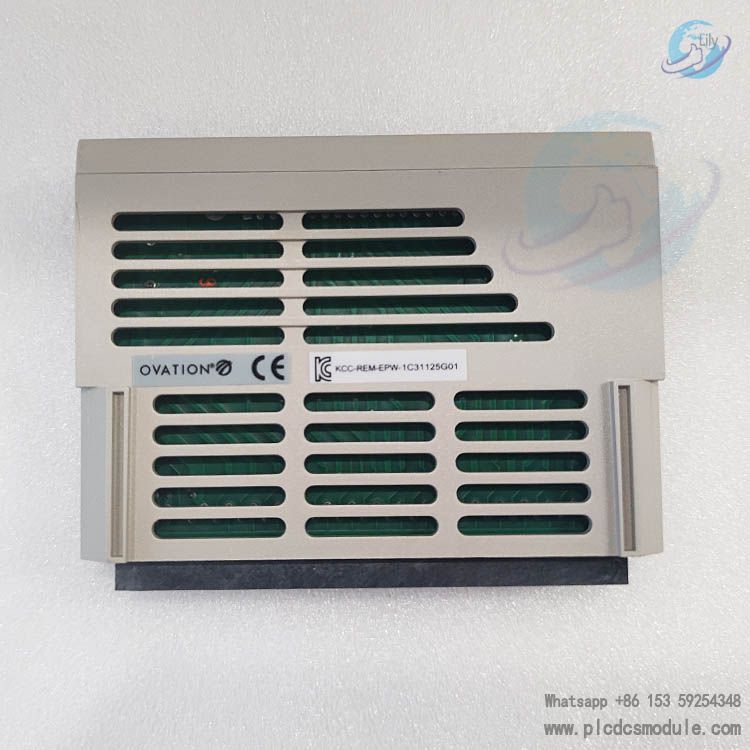
Note; All products on this site are special products, the market price has been fluctuating, the specific customer service offer shall prevail, because the product is a new product, the picture is not a real shot, please confirm with customer service before placing an order model and product, price and other details, the site used, new are for sale, please contact customer service communication. The 1C31125G01 is a digital output module in the Ovation system. It works in conjunction with the Electronics module 1C31122G01 to provide 16 channels of single-ended digital outputs. It can convert digital signals from the control system into actual control outputs, which are used to drive external devices such as relay coils and lighting fixtures. Additionally, it supports interface with relay panels to expand switching capabilities.
Technical Parameters
| Parameter | Details |
|---|
| Output Channels | 16 Single-ended Digital Outputs |
| Output Voltage Range | 0–60 VDC |
| Maximum Current per Channel | 500 mA |
| Total Current Limitations | 890 mA (Group 1)
2.2 A (Group 2/3 when used with relay panel) |
| Off-State Voltage (Max) | 60 VDC |
| On-State Voltage (Max) | 1.0 V @ 500 mA; 0.2 V @ 100 mA |
| Propagation Delay | Maximum 2.5 ms (Rload=500Ω) |
| Isolation Voltage | 1000 V AC/DC between channels and logic |
| Operating Temperature | 0 to 60°C (32°F to 140°F) |
| Storage Temperature | -40 to 85°C (-40°F to 185°F) |
| Humidity (Non-condensing) | 0–95% |
Functional Features of 1C31125G01 Digital Output Module:
Flexible Output Control:
- Directly supports controlling 5–60 VDC loads.
- Expandable to higher current/voltage scenarios via relay panels, compatible with various types such as solid-state relay panels and G2R relay panels.
Comprehensive Protection Mechanisms:
- Short-circuit and overcurrent protection.
- Monitors field power supply status via fuse detection circuit; indicates fuse failure through external error LED (E) and Status Register Bit6.
Diagnostics and Status Indication:
- Integrated LEDs for P (Power), C (Communication), E (External Error), I (Internal Error), and CH1–CH16 (Channel Status) provide real-time feedback on module operation.
- Configurable communication timeout period (62 ms–16 s) via configuration register; supports options to maintain or disable outputs upon timeout.
Reliable Isolation Design:
- Isolated from backplane and other cards to prevent noise and interference, ensuring stable operation in industrial environments.
Configuration and Registers
- Configuration Register (Address 13 / D in Hex): Sets parameters for module configuration, forced errors, communication timeout, timeout actions, and fuse detection enable.
Status Register (Address 13 / D in Hex): Provides feedback on module configuration status, error conditions, timeout settings, and fuse detection results.
Installation and Wiring
Terminal Connections:
Includes output positive terminals (+), common terminals, auxiliary power terminals (PS+/-), and shield terminals (SH). For specific wiring details, refer to the terminal block wiring diagram.
CE Certification Requirements:
- When hazardous voltages (>30 V RMS, etc.) are involved, a warning label (1B30025H01) must be affixed.
- Field wiring should use braided shielded cables, with grounding at the cabinet entrance.




 3005319639