


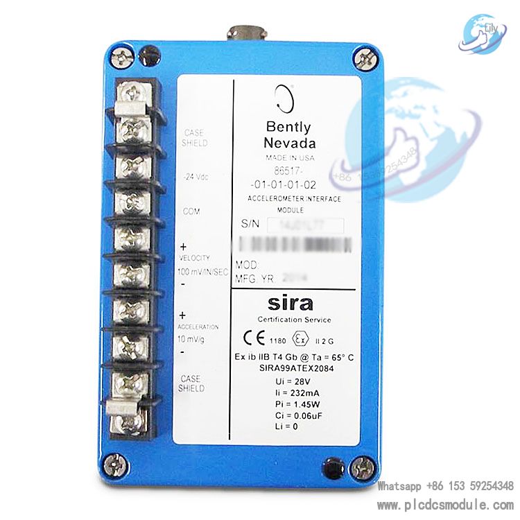
Bentley Nevada 86517-01-01-01-02 Accelerometer Interface Module.The 86517-01-01-01-02 accelerometer interface module is a component of accelerometer-based sensor systems. It is mainly used for vibration monitoring of aero-derived gas generators and gas turbines. It is compatible with the 3300/95 filter module/vibration monitor of the Bently Nevada 3300 series, and can also be used with specially modified 3300 series monitors such as the 3300/15 and 3300/25.
Model Interpretation (86517-01-01-01-02)
According to the model coding rules in the ordering information, the meanings of each part of this model are as follows:
86517: The base model of the product, i.e., the accelerometer interface module.
AXX=01: Option for sensor charge input sensitivity, corresponding to 50 pC/g.
BXX=01: Option for filter cutoff frequency, corresponding to a 25 Hz high-pass cutoff frequency and a 350 Hz low-pass cutoff frequency.
CXX=01: Option for DC signal bias voltage, corresponding to -10 Vdc.
DXX=02: Option for institutional certification, corresponding to CENELEC (SIRA) certification.
DATA SHEET
![]() Bently Nevada Asset Condition Monitoring.pdf
Bently Nevada Asset Condition Monitoring.pdf
Core Functions
Convert the charge input of the accelerometer into a voltage acceleration signal.
Scale the voltage signal to 10 mV/g peak (1.02 mV/m/s² peak).
Buffer the acceleration signal to enable connection to instruments via long cables.
Perform band-pass filtering on the acceleration signal using a 12th-order filter (the cutoff frequency is determined by the BB option).
Integrate the filtered acceleration signal to convert it into a velocity signal with a sensitivity of 100 mV/in/s peak (3.94 mV/mm/s peak).
Buffer the velocity signal to enable connection to monitoring instruments via long cables (velocity signals are typically used for machine monitoring).
Power Supply: The supply voltage ranges from -23 Vdc to -26 Vdc, with a maximum current consumption of 22 mA.
Input: Receives differential input from piezoelectric accelerometers, with sensitivities of 50 pC/g peak or 100 pC/g peak. The overload capacity is 50,000 pC peak (for accelerometers with 50 pC/g peak sensitivity) and 100,000 pC peak (for accelerometers with 100 pC/g peak sensitivity).
Acceleration Output: It features a balanced output with a sensitivity of 10 mV/g peak (1.02 mV/m/s² peak) and a nominal output impedance of 50 ohms. The typical dynamic range is 750 gs (7350 m/s²) without a barrier and 500 gs (4902 m/s²) with a barrier. For frequency response, the low-frequency response is controlled by the charge amplifier, with a -3 dB cutoff frequency of 4.7 Hz; the high-frequency response is affected by multiple factors, and the upper -3 dB frequency is approximately 5000 Hz under specific capacitance conditions.
Velocity Output: It has a balanced output with a sensitivity of 100 mV/in/s peak (3.93 mV/mm/s peak) and a nominal output impedance of 100 ohms. The dynamic range is 20 in/s peak (508 mm/s peak) (25 Hz to 1000 Hz), and the frequency response depends on the filter.
Filter: The high-pass and low-pass cutoff frequencies are 25 Hz and 350 Hz, respectively, with 6th-order filters. The roll-off rate is -36 dB per octave, featuring a Butterworth response, and the attenuation at the cutoff frequency is -3 dB ±0.5 dB.
Environment: Operating temperature ranges from 32°F to 158°F (0°C to 70°C); storage temperature ranges from -40°F to 185°F (-40°C to 85°C); humidity ranges from 0 to 95% without condensation.
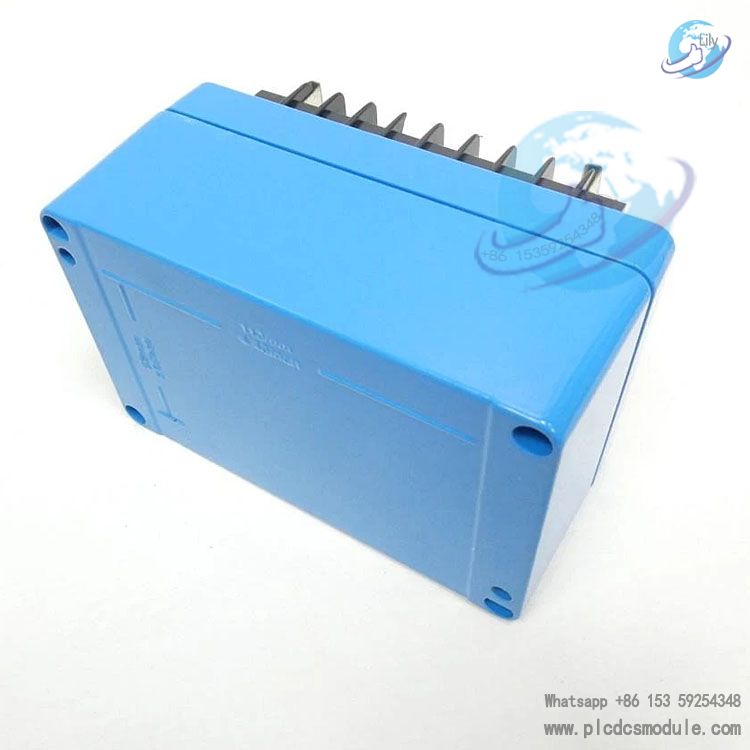
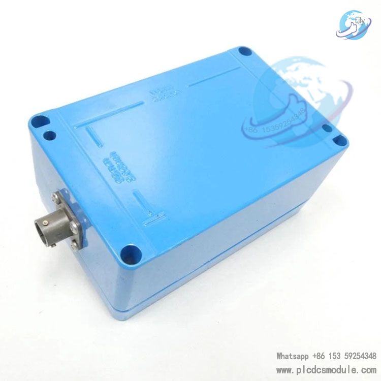
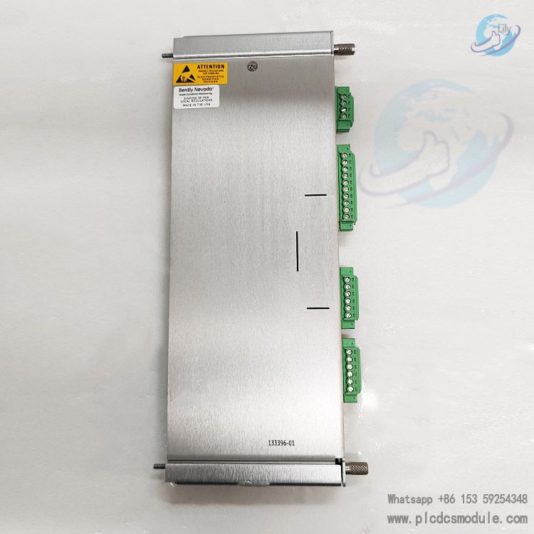
Mechanical: The accelerometer input connector is MS - 3112 - 8 - 3P; the power supply/output connector is an 8-terminal terminal block. Dimensions are 3.00 inches (76.2 mm) in height, 3.25 inches (82.6 mm) in width, and 5.50 inches (139.7 mm) in length. The mounting method uses two 8-32 socket head cap screws with a diameter of 0.16 inches, located at the diagonal positions of a 4.45-inch × 2.05-inch (113 mm × 52 mm) rectangle. The interface module must be isolated from the ground.
Reception, Inspection, and Handling: After removing from the shipping container, check for transportation damage. If not used immediately, it should be placed back into the container, sealed, and stored in an environment free from high temperature, high humidity, and corrosive atmospheres.
Module Installation:
Accelerometer Installation:
Field Wiring:
Installation in Hazardous Areas: If installed in a hazardous area, it must meet the certification requirements of relevant institutions. For example, CENELEC-certified systems need to attach system cable labels to the field wires of the interface module and use the...
Calibration and Velocity Signal Path Verification:The acceleration output is calibrated at the factory and can be recalibrated if necessary. This requires tools such as a function generator, DC power supply, and multimeter, and is performed using a calibration assembly composed of specific capacitors and connectors.
For velocity signal path verification, set the frequency and amplitude of the function generator according to the filter cutoff frequency and accelerometer charge sensitivity, and measure whether the +VELOCITY output is within the specified range (0.3535 Vrms ± 18.0 mVrms).
Common Mode Rejection Measurement: It is recommended to perform this every two years to ensure that the module output noise meets the design specifications. After inputting a specific signal, verify that the "+ ACCEL" output is less than the specified value.
Troubleshooting:
Customers who purchased this product are also browsing the following products:
Bently Nevada 2300/25 Vibration Monitors
Bently Nevada 159840-01Acceleration Interface Module
BENTLY NEVADA 106M1079-01 3500/15 Universal AC Power Supply
Rockwell ICS TRIPLEX T8110B Trusted TMR Processor Module


 3005319639