Note; All products on this site are special products, the market price has been fluctuating, the specific customer service offer shall prevail, because the product is a new product, the picture is not a real shot, please confirm with customer service before placing an order model and product, price and other details, the site used, new are for sale, please contact customer service communication. The
IC697BEM731 is a Genius I/O Bus
Controller Module belonging to the Series 90-70, which is specifically designed for the GE Series 90-30 Programmable Logic Controller (PLC) system. As the core bus control unit of the system, this module features single-channel control capability, enabling key functions such as I/O data transmission, global communication, and fault diagnosis and handling. It supports redundant configuration, handheld monitoring connection and multiple communication protocols, and is widely used in scenarios requiring stable and efficient industrial control communication, providing reliable support for data interaction between multiple PLCs and upper computers.
Designed in compliance with VME Standard C.1, it can be flexibly configured via MS-DOS or Windows-based programming software, and is compatible with bus cables of varying lengths and types, satisfying the diverse installation and application requirements of industrial field environments.
related documents
 IC697BEM731.pdf
Core Features
Channel & Expansion Capability
It adopts a single-channel design, with each channel supporting up to 30 drops. It enables flexible expansion of I/O node quantity, meeting the device connection requirements of medium-to-large industrial control scenarios.
Diagnostic & Redundancy Support
It integrates the IC66 (IC660 or IC661) I/O diagnostic function*, which can monitor the status of the bus and devices in real time and feed back fault information. The module supports redundant configurations of modules, cables and CPUs, improving system reliability and preventing system interruption caused by single-point failures.
Multi-Functional Communication Capability
It supports Global Communications, enabling automatic repeated transmission of global data between multiple CPUs. It is compatible with IC66 LAN communication* and supports datagram transmission; point-to-point communication or bus broadcasting can be realized via ladder logic commands. A Hand Held Monitor Port is provided to facilitate on-site direct debugging and status checking.
Software Configuration & Integration
It allows software configuration via the PLC CPU, eliminating the need for hardware jumpers to adjust key parameters. It works in conjunction with the alarm processor function of the IC697 PLC, marking faults with timestamps and storing them in a queue, which facilitates fault tracing and analysis.
Main Functions
I/O Data Processing
The module occupies a single IC66* PLC slot and asynchronously scans IC66* I/O modules. It transmits I/O data to the CPU via the backplane of the IC697 PLC rack upon each scan, ensuring real-time data synchronization. Meanwhile, it receives output commands and control instructions (e.g., clearing circuit faults) issued by the CPU and updates them to the corresponding I/O modules.Communication Node Function
It can serve as a communication node to connect other bus controllers, PCIM modules and IC66* devices via the IC66* bus, establishing a communication network between multiple PLCs and upper computers and supporting peer-to-peer data transmission.Fault Management
Faults reported by the bus controller are centrally managed by the PLC alarm processor. Fault information is recorded with timestamps and stored in tables, facilitating user inquiry and troubleshooting.Command Interaction Support
It performs command interaction with the CPU via a communication window, supporting 15 categories of core commands including pulse test output, configuration read/write, diagnostic information read, global output enable/disable, and datagram transmission. These functions satisfy the requirements for system debugging, configuration and operation control.
Installation & Removal
Installation Procedures
- Refer to the corresponding PLC installation manual before installation to ensure compliance with operational standards.
- Power off the rack to prevent damage to the module or system caused by hot swapping.
- Install the module into the designated slot of the PLC rack (refer to Figure 1 for the typical system configuration).
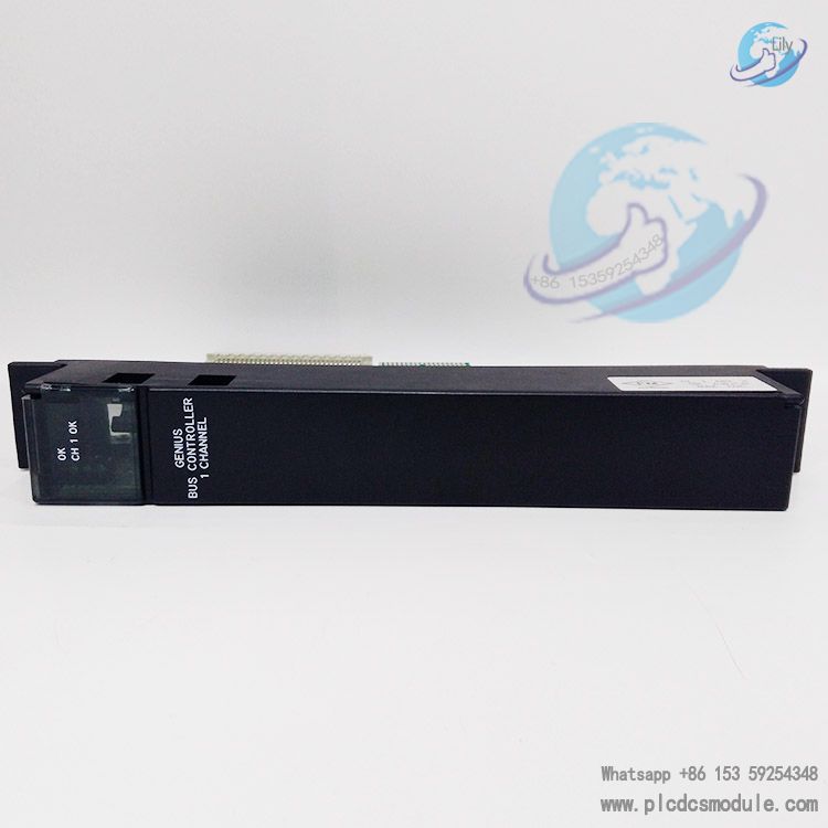
- Power on the system. The top LED of the module will flash for approximately 5 seconds after power-on; upon completion and success of diagnosis, the top LED remains steadily lit. When a valid configuration is received from the CPU and the normal operation of the IC66* I/O bus is verified, the middle LED turns on. The bottom LED remains off under all circumstances.
Special Installation Requirements
- The Bus Transmitter Module IC697BEM713A shall be installed on the right side of GBC/NBC or other IC697 I/O modules; IC697BEM713B may be installed adjacent to the CPU.
- All racks must maintain the same ground potential, with a maximum support of 8 racks.
- The total length of all interconnection cables from the BTM to the last BRM shall not exceed 15 meters. The maximum length of the IC66* I/O bus can reach 2285 meters (7500 feet).
Removal Procedures
- Press the front face of the module housing with the thumbs of both hands, hook the plastic buckles on the back of the housing with fingers, and firmly grip the top and bottom of the module.
- Squeeze the rack buckles on the back of the housing to disengage the buckles from the rack guide rails, then pull the module out of the backplane connector with force.
- Slide the module along the card guide rails and remove it from the rack to avoid collision with other modules.
Bus Operation & Configuration
Bus Operation Mechanism
- The IC66* I/O serial bus transmits data between devices on the bus via the token-passing method. Bus scanning is independent of the IC697 PLC CPU scanning.
- During bus scanning, the controller receives input data and fault information from all I/O modules, sets diagnostic status parameters, updates output data of I/O modules, and issues CPU commands to target devices simultaneously.
- In the I/O service phase of CPU scanning, the controller provides all discrete input and analog input data to the CPU, receives current output commands and new instructions issued by the CPU, and reports the operating status of itself and the serial bus.
Key Configuration Parameters
Baud Rate Setting
- The default baud rate is 153.6 Kbaud (Standard), supporting a maximum bus length of 2000 feet.
- It can be adjusted via MS-DOS or Windows-based programming software to 153.6 Kbaud (Extended, supporting 3500 feet), 76.8 Kbaud (supporting 4500 feet), or 38.4 Kbaud (supporting 7500 feet).
- All devices on the bus must be set to the same baud rate; otherwise, the bus cannot operate normally.
Serial Bus Address
- The default address is 31, and alternative addresses can be configured via MS-DOS or Windows-based programming software.
Dual-Bus Configuration
- Supports the construction of a dual serial bus system via Bus Switching Modules (BSMs) to provide an alternate communication path.
- The dual bus must be supported by different CPUs; bus controllers under the same CPU do not support redundant buses.
- Modules on the stub are connected via short-distance unterminated cables. It is necessary to plan cable lengths and module layouts in advance and refer to the BSM data manual (GFK-0072).
Wiring Specifications
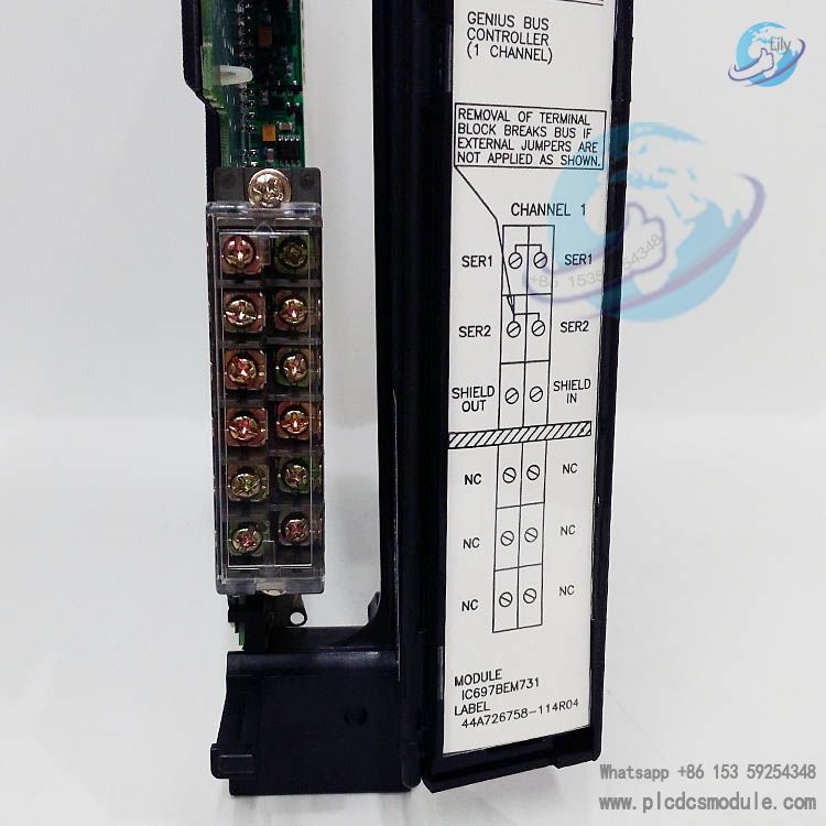
Interface Definition
- The 3PL connector of the module serves as the field terminal connection port for the IC66* bus, including key connection points such as SER1, SER2, SHIELD IN, and SHIELD OUT.
- The 1PL port is the connection port for the handheld monitor.
Cable Requirements
- Shielded twisted-pair cables must be used. All cables on the same serial bus shall be of the same type; different buses (not connected via BSMs) can use different types of cables.
- Cable specifications shall refer to Table 2, with parameters such as impedance, conductor count, rated voltage, and operating temperature to be matched (e.g., Belden 9182 cable features 2-core #22 conductors, 150-ohm impedance, supports 30V voltage and 60℃ ambient temperature).
Termination Matching
- Both ends of the serial bus must be matched with characteristic impedance terminating resistors. The module is supplied with two types of resistor packs (44A730116-G01 for 150 ohms, 44A730116-G02 for 75 ohms) and prefabricated terminal plugs (75-ohm plug: 44A713909-004; 150-ohm plug: 44A713909-003).
- If the module is located at the bus end, the terminating resistor with corresponding impedance shall be selected based on cable length and type.
Customers who purchased this product are also browsing the following products:
GE DS6800CCIE1F1D Power Distribution Module
GE IC693MDL231 AC Isolated Input module
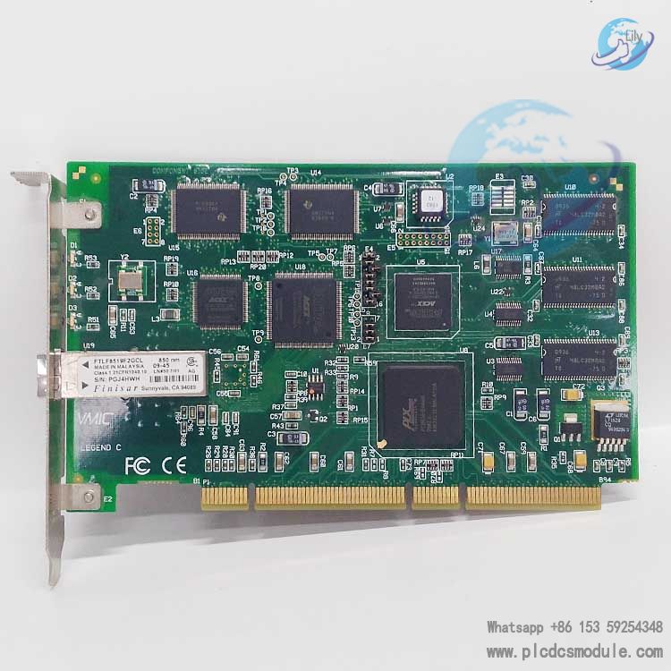
GE VMIVME-3122-210 High-Performance ADC Card
GE IS215UCCCM04AB| Mark Vi | CPCI Controller Board


 3005319639