IS200VTURH1BAC is a VME bus main turbine protection board matched with GE Speedtronic Mark VI control system. Serving as the core safety monitoring hardware for gas turbine and steam turbine units, this complete hardware unit is built based on the Triple Modular Redundancy (TMR) architecture. It undertakes four core functions: hard overspeed protection for turbine units, shaft electrical condition monitoring, flame probe signal acquisition, and generator grid connection logic control.
Integrated with multi-channel signal acquisition circuits, trip relay drive loops and status indication units, the hardware is compatible with both simplex and triple-redundant system configurations. It acts as an indispensable safety barrier inside turbine control cabinets of power plants and petrochemical refineries.
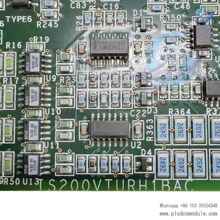
Technical Features
High-precision signal acquisition: The rotational speed pulse input range covers 2 Hz to 20 kHz, with a measurement error not exceeding ±0.05% of the reading. It can identify low-speed probe signals with a peak value of merely 27 mV and maintain stable detection under zero-speed operating conditions.
Complete hardware trip circuit: It directly drives three groups of overspeed trip relays on TRPx terminal boards without intermediate arithmetic processing. Upon overspeed triggering, the unit operating circuit is cut off at the hardware level to eliminate risks caused by software failure.
Multi-channel synchronous monitoring: A single board supports signal acquisition from 8 Geiger-Müller flame detectors, while synchronously monitoring turbine shaft induced voltage and shaft current. Audible and visual alarm signals are output immediately once parameters exceed safe thresholdsVBR Turbin....
Wide-temperature industrial adaptability: The operating ambient temperature ranges from -30℃ to +65℃, with humidity ranging from 5% to 95% without condensation. It adopts a 1500 Vrms electrical isolation design to resist electromagnetic interference at power plant sites.
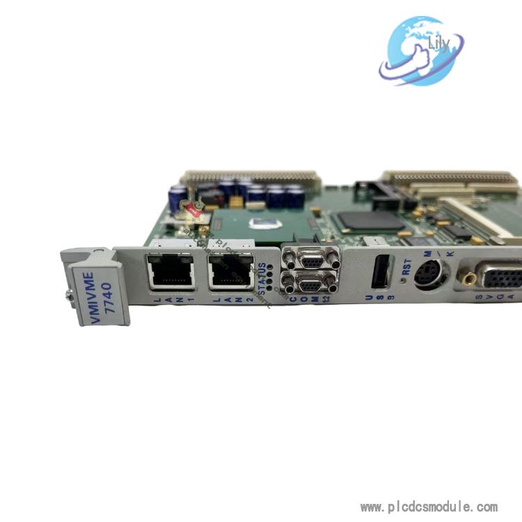
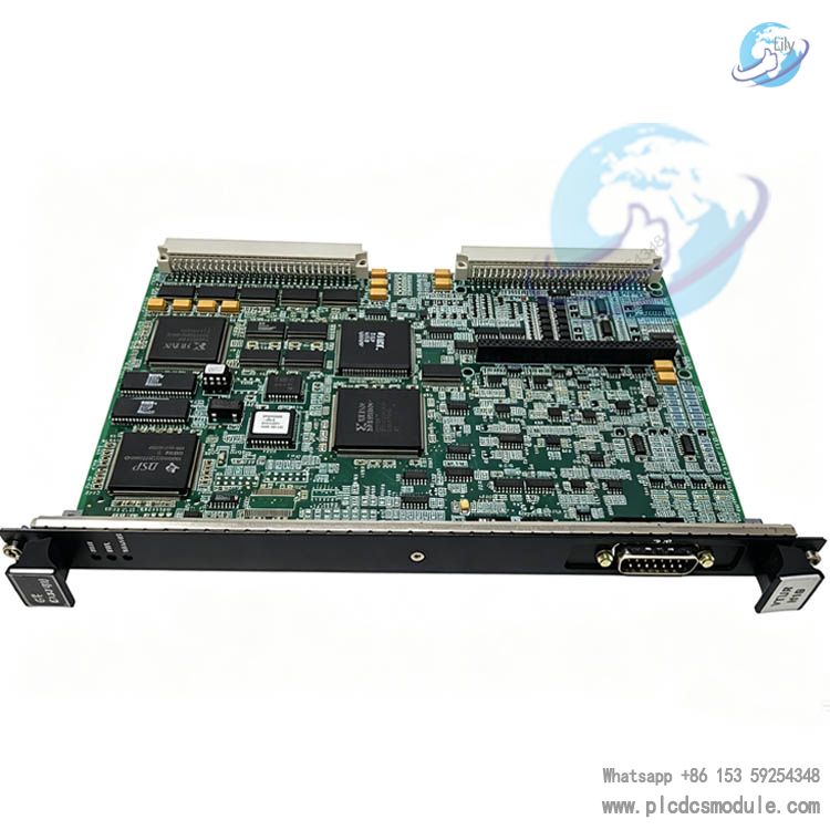
Standard single-slot VME mounting structure. The front panel is equipped with three LED status indicators and a dedicated J5 cable interface. The panel and PCB are fixed with three screws for convenient disassembly, installation and maintenance.
Compatible with both redundant and simplex configurations. Under the TMR triple-module redundant setup, three boards perform parallel arithmetic and majority voting; under simplex configuration, a single board can independently complete all protection and monitoring functions.
Part Number Breakdown
Segment-by-segment interpretation of the full part number IS200VTURH1BAC:
- IS200: Product series code, representing the general category of dedicated I/O and protection boards for Mark VI control systems.
- VTUR: Functional abbreviation for VME Turbine Protection, denoting a dedicated VME bus turbine protection board.
- H1: Hardware revision generation; H1 refers to the first-generation hardware circuit design.
- B: Base board primary revision number.
- AC: Suffix differentiation code, representing a customized configuration integrated with complete flame monitoring and overspeed trip circuits, which distinguishes it from the simplified base model IS200VTURH1B.
Product Characteristics
Hardware Structural Characteristics
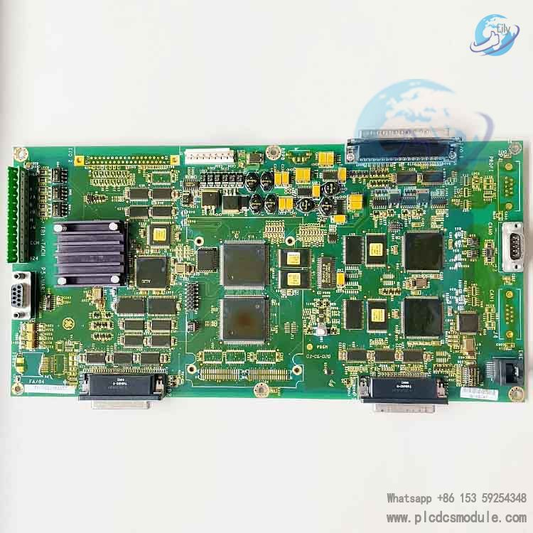
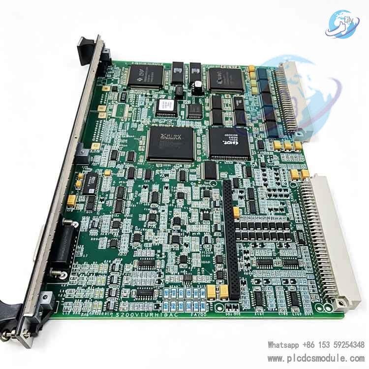
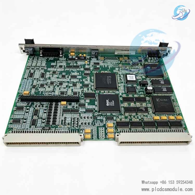
The board’s PCB is populated with over 60 integrated circuits, 13 signal transistors, and a large number of resistors and capacitors. It integrates dedicated voltage conversion transformers, heat dissipation units, and fuse protection circuits. Dual backplane connectors realize cabinet bus communication, and multi-pin female connectors interface with signal circuits of external terminal boards.
Functional Characteristics
- Overspeed ProtectionIt collects pulse signals from magnetic reluctance speed probes and calculates turbine rotational speed in real time. When readings exceed thresholds, it directly drives trip relays to output hard shutdown signals, serving as the primary safety protection for turbine units.
- Shaft Electrical MonitoringBrushes collect induced voltage to ground and leakage current from turbine shafts. Continuous alarms are issued when readings exceed limits to prevent bearing corrosion caused by shaft current.
- Flame Condition MonitoringFor gas turbine applications, 8 flame detectors are connected to judge the presence or absence of combustion chamber flames in real time. Flame loss triggers interlock logic to reduce unit load or initiate shutdown.
- Generator Synchronization ControlIt collects bus voltage and generator terminal voltage, cooperates with the excitation system to complete automatic unit grid connection, and controls synchronous relays and main circuit breaker coils.
Operational Reliability Characteristics
It adopts hardware majority voting logic. Under redundant architecture, median-value arithmetic is performed on three channels of collected signals; failure of a single channel will not affect overall protection functions. Full-circuit electrical isolation prevents false protection actuation induced by external strong electrical interference. Designed for 7×24-hour continuous full-condition operation, it meets the demand for year-round uninterrupted operation of generator setsCSDN文....
Application Fields
- Main control cabinets of gas turbines and steam turbines in thermal power plants
- Combined-cycle turbine control systems for self-owned power stations in refining and chemical plants
- Safety monitoring systems for distributed power generation turbine units at oil and gas fields
- Turbine generator set control cabinets of self-owned power workshops in steel plants
- Protection and control units for industrial large-scale waste heat power generation turbine units
Operating Principle
The board exchanges data with the main controller card of the Mark VI system via the VME backplane bus. After analog signals from external sensors are fed into this board through terminal boards, electromagnetic clutter is first filtered out by isolation circuits, followed by analog-to-digital conversion and numerical calculation carried out by onboard arithmetic circuits.
The rotational speed monitoring circuit independently collects pulse frequencies from multiple magnetic reluctance probes. The hardware circuit converts signals into turbine speed readings in real time. Once the speed exceeds the preset safety threshold, the onboard relays are driven directly without waiting for instructions from the main controller processor. Shutdown signals are sent to the trip circuits of TRPx terminal boards to implement hardware-level overspeed protection, eliminating the risk of protection failure caused by software crashes.
After shaft voltage and flame detector signals are processed by acquisition circuits, one branch locally drives LED status indicators to visually display channel conditions, while the other branch uploads data to the system main controller over the VME bus for generating real-time curves and alarm logs on the upper computer. In redundant systems, three IS200VTURH1BAC boards collect the same set of sensor signals simultaneously. Valid values are determined via 2-out-of-3 voting logic. If one board malfunctions, the other two fully functional boards take over all protection functions without triggering false unit shutdowns.
For grid synchronization control, the board collects phase and amplitude data of grid bus voltage and generator terminal voltage. Signals are transmitted to Mark VI regulation cards to realize phase matching in coordination with the excitation system. Synchronization signals are output to circuit breaker control loops to complete safe grid connection of the unit.
Product Comparison
Horizontal comparison of similar turbine protection and signal acquisition boards within the Mark VI series
IS200VTURH1BAC vs IS200VTURH1B
IS200VTURH1B is a basic simplified model that only supports overspeed and shaft voltage monitoring, without the 8-channel flame detector acquisition circuit. IS200VTURH1BAC expands flame monitoring and generator synchronization control functions to meet full protection requirements of gas turbines, with a greater number of hardware interfaces.
IS200VTURH1BAC vs IS200TREGS1B
IS200TREGS1B is an emergency trip terminal board solely responsible for power output to trip solenoid valves, with no capability for sensor signal acquisition. IS200VTURH1BAC serves as the core front-end for signal acquisition and calculation. It works in tandem with TREG boards, forming a complete protection loop consisting of one processing board and one terminal board.
IS200VTURH1BAC vs IS200VTCCH1CBB
IS200VTCCH1CBB is a thermocouple temperature acquisition board that only collects analog temperature signals and contains no unit shutdown protection logic. The VTUR board focuses on safety trip protection. The two belong to separate functional modules for temperature monitoring and unit protection respectively, working collaboratively to realize full-parameter monitoring of turbines.
IS200VTURH1BAC vs IS200VPWRH1AHD
IS200VPWRH1AHD is a cabinet power distribution board only tasked with system power conversion, without signal acquisition or protection arithmetic capabilities. The VTUR board is a functional processing board supplied with stable operating voltage by the VPWR power board.
Matching Supporting Products
Mandatory Matching Hardware
- IS200TRPAH1BEC Turbine Protection Terminal BoardActs as the intermediate wiring carrier for all external signals of this board.
- IS200TREGS1B Emergency Trip Terminal BoardReceives trip signals from this board and drives unit shutdown solenoid valves.
- IS200VCMIH2BEE Mark VI System Main Control Communication CardEnables data exchange between the protection board and the upper computer.
Auxiliary Supporting Hardware
- IS200VPWRH1AHD Cabinet DC Power Supply BoardSupplies 24VDC operating power to all VME boards in the rack.
- IS200VTCCH1CBB Thermocouple Acquisition BoardWorks alongside the VTUR board to collect temperature data of turbine casings and exhaust gas.
- Magnetic Reluctance Speed Probes, Geiger-Müller Flame Detectors, Shaft Voltage Collector BrushesField sensors for rotational speed, flame status and shaft electrical signal acquisition.
- Mark VI HMI Human-Machine Interface TerminalUsed for parameter configuration, real-time status monitoring and fault code inquiry.
FAQ
Q1: How to distinguish IS200VTURH1BAC from the simplified model IS200VTURH1B during procurement?
A1: Check the full suffix of the part number. Models with the AC suffix come with an 8-channel flame monitoring circuit, while the basic model suffixed B has no flame acquisition channels. In addition, check the PCB silkscreen and side nameplate of the board; the complete part number IS200VTURH1BAC will be marked clearly.
Q2: Does this board support Mark VIe control system, or is it only compatible with Mark VI?
A2: IS200VTURH1BAC is only compatible with racks adopting the traditional Mark VI VME bus architecture and cannot be directly applied to distributed Mark VIe systems. Dedicated protection modules from the VIe series shall be selected for Mark VIe systems.
Q3: What are the basic troubleshooting steps if the board generates a channel signal loss alarm on site?
A3:
- Power off the system and inspect whether the J5 cable and wiring on the TRPA terminal board are loose or oxidized;
- Conduct cross-testing by replacing with a spare board of the same model to determine whether the fault lies with the board itself or external sensors;
- Clean dust accumulated on terminals of the terminal board and re-tighten all wiring connections.
Q4: Is a full unit shutdown required to replace a faulty single VTUR board under triple-module redundant configuration?
A4: A full unit shutdown is not required. The other two boards in the redundant architecture can independently implement all protection and monitoring functions. The faulty board can be replaced during a low-load maintenance window: power off the corresponding slot, swap the defective board, and the system will automatically complete channel synchronization after replacement.
Q5: What on-site parameters shall be provided together when purchasing spare parts to avoid wrong model delivery?
A5: It is necessary to provide the cabinet system model (Mark VI), the full part number of the existing board, the model of gas/steam turbine, whether flame detector signal acquisition is required on site, and the number of slots on the cabinet VME backplane.
Q6: The LED indicators fail to light up after long-term operation of the board. What is the most probable fault cause?
A6:
- First, verify whether the 24VDC output voltage of the cabinet VPWR power supply board is normal;
- Second, check if dust accumulation causes short circuits on the gold fingers of VME backplane slots;
- If the above checks show no abnormalities, the internal power conversion circuit of the board is damaged, and the spare board needs to be replaced directly.
Q7: Can a simplex system be later retrofitted to a TMR triple-redundant architecture? What additional hardware is required?
A7: Retrofit is feasible. Two additional IS200VTURH1BAC boards of the same model and two matching sets of IS200TRPA terminal boards need to be added. Meanwhile, the number of slots on the cabinet VME backplane shall be expanded, and the system control configuration program shall be revised accordingly.
Q8: Do the stored protection threshold parameters need to be re-entered after replacing the spare board?
A8: Parameters need to be re-downloaded. The board has no local parameter storage unit; all protection thresholds and channel parameters are stored inside the Mark VI main control card. After spare board replacement, download the corresponding unit configuration parameters via the HMI upper computer to restore normal operation.
Recommended Product Models of the Same Series
- IS200VTURH1BAC Main Turbine Protection Board
- IS200TRPAH1BEC Turbine Protection Terminal Board
- IS200TREGS1B Emergency Trip Terminal Board
- IS200VCMIH2BEE Mark VI Main Control Communication Card
- IS200VPWRH1AHD DC Power Distribution Board
- IS200VTCCH1CBB Thermocouple Terminal Board
- IS200VRTDH1DAB RTD (Resistance Temperature Detector) Input Board
- IS200VROCH1BBR Valve Position Servo Control Board
- IS200VVIBH1CAB Vibration Signal Input Board
- IS200VCRCH1BBB Current Signal Acquisition Board
- IS200EPMCH1A IONet Communication Daughter Card
- IS200JPDDG1AAA DC Power Distribution Terminal Board
- IS200SPROH1ADD Spare Protection Terminal Board
- IS200MVRPH1AED Power Supply Monitoring Board
- IS200EHPRG1BBR Pulse Amplifier Board