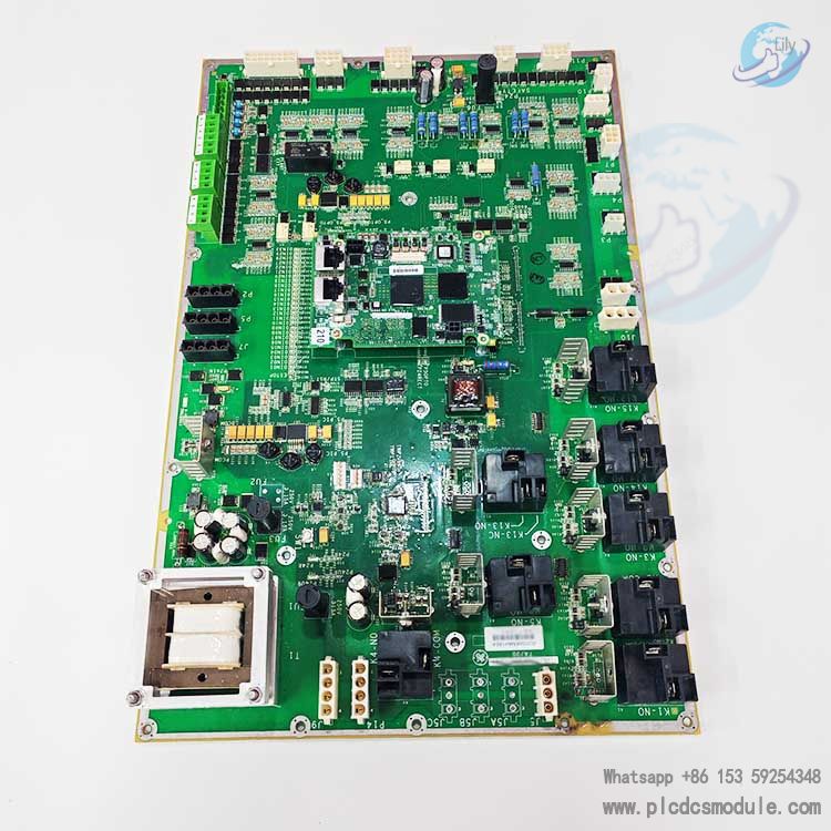
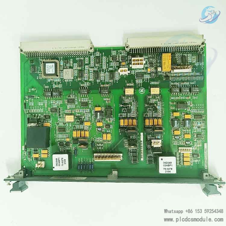
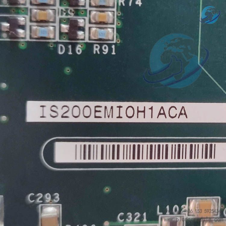
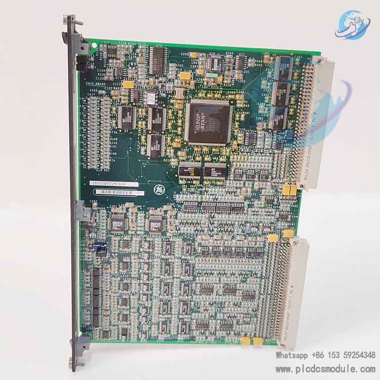
GE IS200EMIOH1ACA is the core main excitation input/output board for the Speedtronic Mark VI EX2100 excitation control system. It serves as the central signal hub of the entire excitation cabinet and is compatible with the excitation regulation loops of gas turbine and steam turbine generator units.
The IS200EMIOH1ACA aggregates and processes analog and digital signals transmitted from multiple terminal boards. It performs PT voltage and CT current acquisition, closed-loop excitation regulation calculation, gating pulse output for SCR thyristors, and execution of unit trip interlock logic.
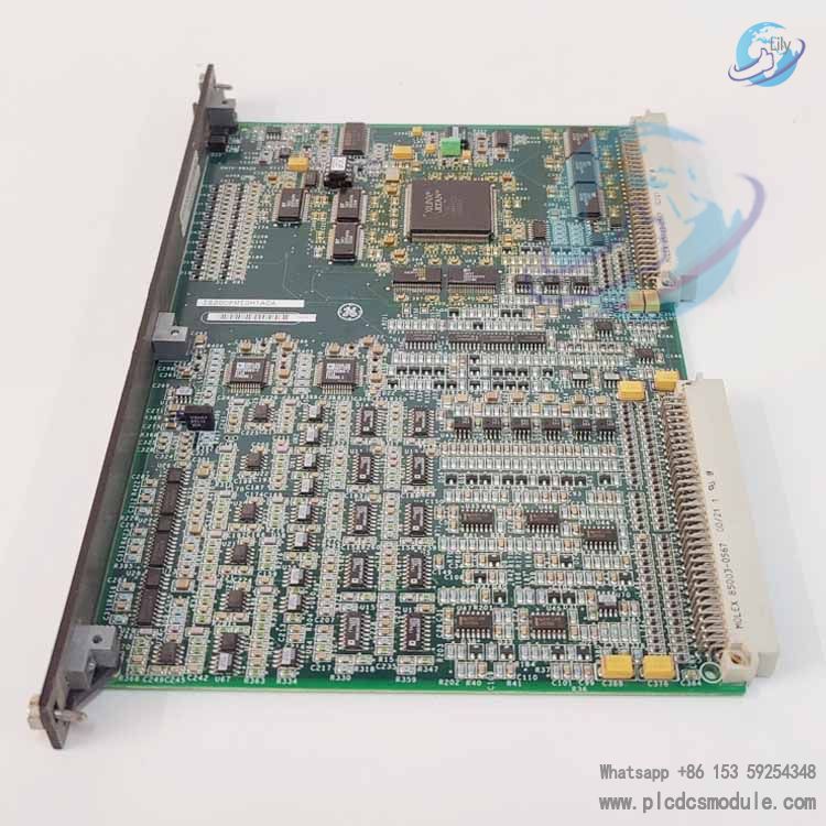
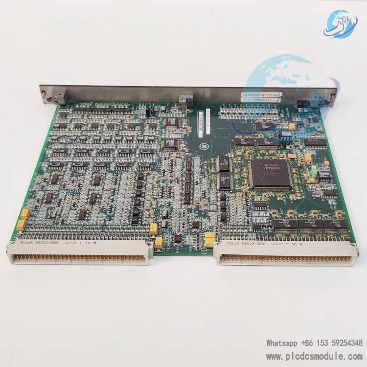
Adopting a single-slot double-height standard VME form factor, this board can be directly installed into standard Mark VI control racks. It operates on 24VDC rack power supply and is engineered for round-the-clock continuous operation at power plants.
Technical Features
- Standard double-height single-slot VME hardware structure, compatible with P1 and P2 dual connectors of backplanes for all Mark VI series racks for communication.
- Integrated 512KB flash memory for storing I/O point mapping parameters and 256KB cache for recording operating data logs. No built-in battery is equipped, eliminating the need for regular replacement of energy storage components.
- Equipped with 16 digital input channels, 16 digital output channels, 8 high-precision analog acquisition channels, and supports 12 relay drive channels.
- Two front-mounted LED status indicators are onboard, corresponding to power supply status and overall unit operation fault status respectively, enabling intuitive on-site judgment of board operating conditions.
- Double-layer electromagnetic shielding PCB layout, with a wide operating temperature range of -20℃ to +55℃, delivering strong resistance to severe electromagnetic interference in industrial sites.
- Built-in offline simulation module, allowing excitation logic debugging and fault simulation tests without connection to actual generating units.
- Signal response speed is less than 1ms, meeting the real-time performance requirements of high-speed protection interlocks for generator sets.
Part Number Breakdown
Segment-by-segment decoding of the full part number IS200EMIOH1ACA:
- IS200: Universal series prefix for GE Mark VI IS200 hardware boards, representing VME architecture turbine control boards.
- EMIO: Functional code, abbreviation for Exciter Main Input Output, denoting the main excitation input/output board.
- H1: Hardware revision number, representing the first-generation hardware layout version.
- ACA: Function revision suffix. The first A stands for basic function revision; C indicates compatibility with EX2100 excitation cabinets; the final A represents the mass-production compatible release version.
Product Characteristics
Centralized Signal Management
It interfaces uniformly with four types of terminal boards: EXTB, EACF, ECTB and EPCT. It aggregates signals from voltage and current transducers, dry contact digital signals, relay drive signals, and pilot trip relay drive signals.
Closed-Loop Excitation Regulation
Dual closed-loop algorithms for FVR (Field Voltage Regulation) and FCR (Field Current Regulation) are embedded. They correct generator excitation output in real time to stabilize generator terminal voltage and rotor current.
Pulse Output Control
It calculates and generates thyristor gate control logic pulses, which are transmitted via the rack backplane to ESEL selector boards. The pulses ultimately drive EGPA/EHPA power amplifier boards to complete rectification and voltage regulation.
Built-In Fault Self-Diagnosis
It realizes channel-level signal fault identification, backplane communication disconnection detection, and hardware protection against overcurrent and overvoltage. Fault information is uploaded to the system HMI upper computer in real time.
Modular Compatibility
It is installed in an independent slot; disassembly and replacement will not affect the operation of other boards inside the rack. It supports direct replacement with hardware of the same layout during system renovation and upgrade.
Maintenance-Free Data Storage
Operating parameters are stored in flash memory chips without backup batteries. Parameters will not be lost after long-term unit shutdown and subsequent restart.
Application Fields
- EX2100 excitation control system cabinets for gas turbine and steam turbine generator units in thermal power plants
- Excitation regulation control racks for hydropower generator units
- Turbine unit control stations of self-owned power plants in petrochemical and steel industries
- Gas turbine control units for offshore platforms and distributed energy stations
- Excitation speed regulation control systems for large industrial synchronous motors
Operating Principle
During unit operation, terminal boards including EXTB, EACF, ECTB and EPCT collect analog signals from generator PT voltage transformers and CT current transformers, as well as digital dry contact signals for unit startup/shutdown and protective tripping. All signals are transmitted to the IS200EMIOH1ACA board via the rack backplane.
The internal analog acquisition channels of the board convert analog voltage and current signals into digital data and feed them to the onboard arithmetic chip. The chip executes dual closed-loop regulation algorithms for excitation voltage and current. By comparing preset unit parameters with real-time collected data, it calculates the required gate control pulse timing sequence for thyristors.
Calculated pulse commands are sent down through the backplane to ESEL selector boards, which distribute pulse signals to EGPA/EHPA power amplifier boards to drive rectifier bridge thyristors and realize excitation current regulation. Meanwhile, the board continuously monitors the status of all signal channels. In the event of signal disconnection, out-of-range values or backplane communication failures, internal interlock logic is triggered immediately. Trip drive signals are output to cut off the excitation circuit, and fault codes are uploaded to the upper HMI for fault alarm logging.
Product Comparison
IS200EMIOH1ACA vs IS200DSPXH1D DSP Main Control Board
IS200EMIOH1ACA functions as the excitation I/O signal acquisition and pulse output board, focusing on external signal processing and excitation closed-loop calculation. IS200DSPXH1D serves as the core digital signal processor and overall logic arithmetic unit of the system. It is responsible for overall unit startup/shutdown, speed regulation and general protection logic. The two boards operate cooperatively: the DSP board issues general excitation commands, while the EMIO board completes field signal acquisition and execution output.
IS200EMIOH1ACA vs IS200EPMCH1 AC Feedback Board
IS200EMIOH1ACA covers full-range excitation I/O and pulse control, matching the complete EX2100 excitation system. IS200EPMCH1 only collects AC motor speed and position feedback signals with a single function. It merely acts as an auxiliary signal acquisition board and cannot independently complete closed-loop excitation regulation calculation.
IS200EMIOH1ACA vs IS215PMVPH1A Protection I/O Module
IS200EMIOH1ACA is specially designed for excitation circuits and features the exclusive function of SCR pulse generation. IS215PMVPH1A is a general unit protection I/O board that only processes digital switch signals for unit overspeed, vibration and temperature protection. It lacks high-precision analog signal acquisition and pulse output functions, and the two boards are applied to completely separate circuits.
FAQ
Q1: Can this board be used to directly replace the older version IS200EMIOH1A?
A1: Direct hardware replacement is feasible. Only re-matching EX2100 excitation cabinet parameters via ToolboxST software is required, with no modifications to external wiring terminals.
Q2: What faults does a steady red status LED on the board indicate?
A2: There are three categories of faults:
- Poor contact of the P1/P2 backplane connectors;
- Short circuits or out-of-range readings on analog PT/CT channels;
- Loss of communication with the DSP main control board.First power off the rack, remove and re-seat the board to troubleshoot connection issues.
Q3: What is the operating voltage range of this board, and is it compatible with non-original rack power supplies?
A3: The standard operating voltage range is 18–32VDC, with 24VDC adopted for regular operation. Non-original power supplies are acceptable provided their output voltage remains stable within this range and the ripple factor is less than 5%.
Q4: What mandatory protection requirements apply during transportation and storage?
A4: The board must be fully sealed in an anti-static vacuum bag and packed inside a rigid shockproof carton. Storage ambient temperature shall be maintained between 0°C and 40°C. Do not stack heavy items on top of the board, and keep it away from humid environments and corrosive gases.
Q5: How to resolve signal drift on the board’s analog channels?
A5:
- Power off the system and clean the gold fingers of the terminal board and board connectors;
- Re-calibrate analog channels within ToolboxST software;
- Inspect on-site PT/CT wiring for grounding interference.
Q6: Are there any mandatory bundled purchasing requirements for matching boards when ordering bulk spare parts for project retrofits?
A6: No mandatory bundled purchase rules apply. IS200EMIOH1ACA can be purchased independently. You only need to verify compatibility between the existing rack, DSP main control board and terminal board models.
Recommended Mark VI Series Board Models
IS200EMIOH1ACA Main Excitation I/O BoardIS200DSPXH1D DSP Digital Signal Main Control BoardIS200EPMCH1 AC Feedback Acquisition BoardIS200IGPAG1A Gate Drive Power Supply BoardIS200VAICH1C General Analog I/O BoardIS200VCRCH1A Serial Communication Control BoardIS215PMVPH1A Unit Protection I/O ModuleIS215UCVFH2A Turbine Main Control Circuit BoardIS200TTURH1B Turbine Signal Terminal BoardIS200VSVOH1B VME Servo Control BoardIS200TRPGH1BDF Pulse Signal Conversion BoardIS215VPROH1B Unit Protection Processing BoardIS200WETAH1AEC Wind Power Signal Terminal Assembly