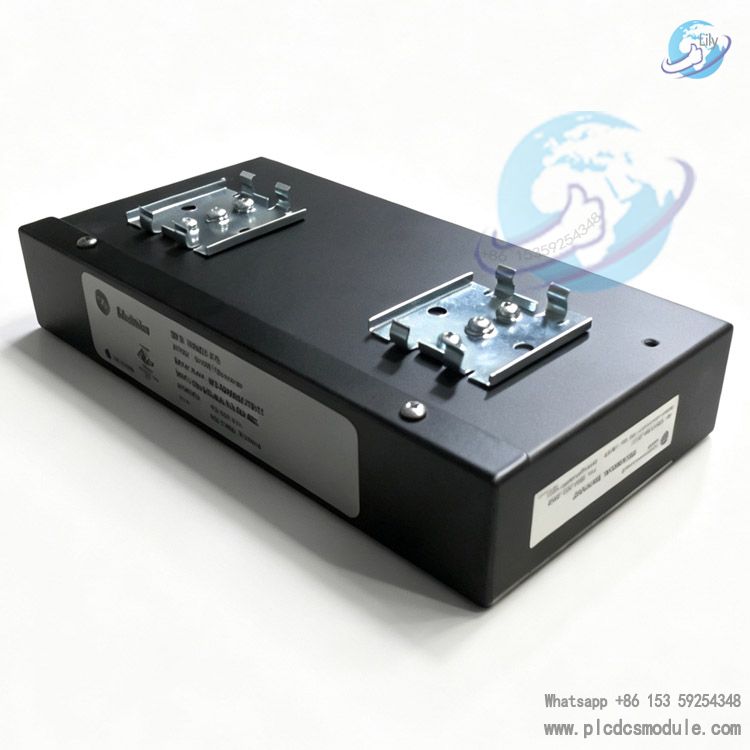
GE MULTILIN MultiNET FE Converter Module - Complete Official Product Guide
1. Product Overview
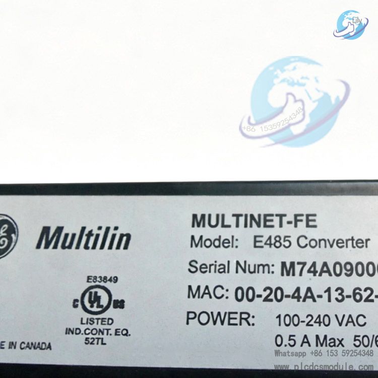
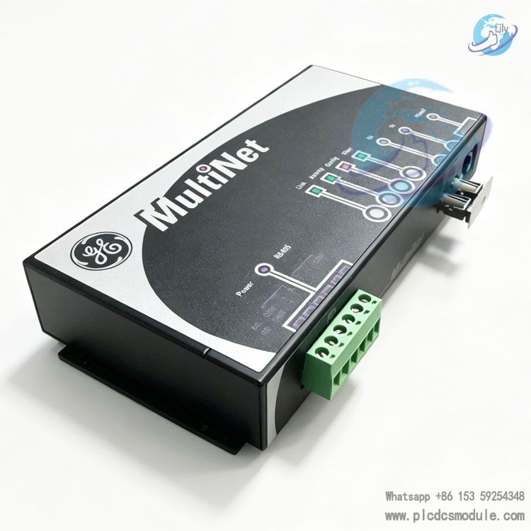
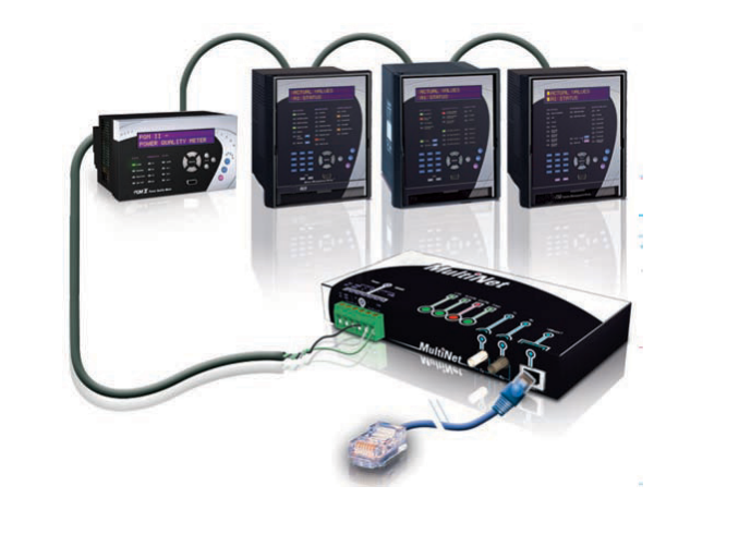
GE MULTILIN MultiNET FE Converter Module is an industrial hardened serial to Ethernet communication gateway developed under GE Vernova Grid Solutions, specially designed for power utility substation and heavy industrial automation scenarios. The core function of MultiNET FE is converting RS485 Modbus RTU serial protocol to standard Modbus TCP/IP over Ethernet, which enables legacy GE MULTILIN serial IED devices to access fiber LAN and WAN monitoring networks. MultiNET FE equips dual network interfaces including 10BaseT RJ45 copper port and 10BaseF 820nm multimode ST fiber port, one single MultiNET FE can connect up to 32 RS485 Modbus RTU intelligent electronic devices simultaneously, eliminating redundant wiring and extra separate protocol converters inside switchgear cabinets. MultiNET FE undergoes full industrial environmental and EMC testing to withstand extreme temperature, surge, electrostatic and RF interference, supporting DIN rail flush mounting for retrofitting existing power panels. All configuration tasks for MultiNET FE can be finished via EnerVista Windows software with plug-and-play operation, making MultiNET FE the primary communication unit for upgrading traditional serial power monitoring systems to Ethernet-based SCADA architecture.
Download

2. Core Functional Advantages
1. Bidirectional Modbus protocol conversion: MultiNET FE translates RS485 Modbus RTU serial frames to Modbus TCP/IP Ethernet packets and reversely decodes TCP commands back to RTU signals, supporting multi-master concurrent communication without data conflict.
2. Dual redundant network transmission channels: MultiNET FE integrates 10BaseT RJ45 copper interface and 10BaseF multimode fiber port. The fiber channel delivers high EMI/RFI immunity and complete electrical isolation for long-distance cross-cabinet or plant-wide communication.
3. High serial bus load capacity: Single MultiNET FE supports up to 32 RS485 connected GE MULTILIN IEDs, reducing hardware quantity and simplifying cabinet cable layout compared with small-sized single-port converters.
4. Full utility-grade industrial hardening: MultiNET FE complies with IEC and IEEE power industry transient protection standards, maintaining stable performance under wide temperature, high humidity and frequent power surge conditions.
5. Flexible installation compatibility: MultiNET FE supports standard 35mm DIN rail mounting and flush bracket installation, requiring no cabinet modification for retrofitting old substation equipment.
6. Simplified one-click configuration tool: EnerVista software automatically scans all online MultiNET FE devices in local network, offering visualized parameter setup, bus diagnosis and IED batch management without custom driver programming.
7. Wide-range dual AC/DC power supply: MultiNET FE built-in universal power circuit accepts both substation DC panel power and factory AC mains, removing the need for extra power transformers.
3. Product Hardware Features
3.1 Communication User Interfaces
RS485 Bus: Isolated 2-wire half-duplex terminal block, baud rate range 300bps to 115.2Kbps, Modbus RTU native protocol.
10BaseT Ethernet: IEEE 802.3 RJ45 copper connector, Modbus TCP/IP protocol support.
10BaseF Fiber: 820nm multimode fiber optic interface with ST connector, long-distance electrical isolation transmission.
3.2 Mechanical Structure Features
Enclosure Material: Full metal shell with IP40 ingress protection rating.
Physical Dimensions: 6.6 inch × 3.98 inch × 1.46 inch.
Mounting Methods: 35mm standard DIN rail mount, flush flat mounting brackets.
Shipping Weight: 2 lbs, compact form factor fits limited panel space inside switchgear.
3.3 Electrical Power Supply Features
DC Input Range: 90V ~ 300V DC, maximum power consumption 5W.
AC Input Range: 100V ~ 240V AC 50/60Hz, maximum apparent power 20VA.
Internal multi-stage transient suppression circuit meets full power EMC standards.
3.4 Environmental Resistance Features
Operating Temperature Range: -20°C to 70°C.
Storage Temperature Range: -40°C to 85°C.
Relative Humidity: Up to 95% non-condensing.
Mechanical Vibration Resistance: Passes 2G mechanical stress test for continuous cabinet vibration scenarios.
Complete EMC Compliance: ESD, surge, fast transient burst, RF radiated & conducted immunity, power frequency magnetic field protection, fully aligned with IEC60255 and EN50263 testing specifications.
3.5 Compliance Certifications
ISO9001 production quality control, UL certification for US & Canada, FCC Part 15 electromagnetic compatibility approval.
4. Complete Technical Specifications
| Category | Parameter Details |
|---|---|
| Protocol Conversion Function | Modbus RTU ↔ Modbus TCP/IP, bidirectional transparent transmission |
| Max RS485 Nodes per MultiNET FE | 32 units of Modbus RTU IED devices |
| Fiber Optical Standard | 10BaseF, 820nm multimode, ST connector |
| Ethernet Rate | 10Mbps 10BaseT, auto half/full duplex adaptation |
| RS485 Baud Rate | 300bps ~ 115200bps, adjustable via EnerVista |
| DC Power Input | 90~300VDC, max 5W power draw |
| AC Power Input | 100~240VAC 50/60Hz, max 20VA |
| Operating Temperature | -20°C ~ 70°C |
| Storage Temperature | -40°C ~ 85°C |
| IP Protection Grade | IP40 |
| Mounting Standard | 35mm DIN rail, flat flush mount brackets |
5. Application Fields of MultiNET FE
1. Substation Integrated Automation System: Multiple bay GE MULTILIN protection relays connect to fiber SCADA back-end via MultiNET FE, realizing remote telemetry, telesignalisation and remote control functions.
2. Industrial Power Room Power Quality Monitoring: PQM / PQM II power quality meters pair with MultiNET FE to upload harmonic distortion, voltage sag and power factor data to local HMI touch screens.
3. Generator Set Monitoring Projects: SR series generator IEDs and ALPS advanced line protection systems build fiber communication networks through MultiNET FE for remote generator operation maintenance.
4. Distributed PV & Wind Power Plant Control: M series and DDS series measurement & control IEDs access plant industrial LAN by MultiNET FE to collect renewable energy output data in real time.
5. Legacy Power System Retrofit Projects: Outdated GE MULTILIN serial IEDs without native Ethernet ports can add MultiNET FE for network communication upgrade, without full replacement of protection equipment.
6. Mining & Factory Motor Protection System: 269 motor management relays wired to MultiNET FE, uniformly uploading motor overload and fault alarm signals to factory DCS control platform.
6. Standard Operation Tutorial for MultiNET FE
Step 1 Hardware Installation of MultiNET FE
Clip MultiNET FE onto DIN rail inside switchgear cabinet, connect AC or DC power terminals; parallel A/B signal wires of all GE MULTILIN IEDs to green RS485 terminal block; plug RJ45 Ethernet cable or ST fiber jumper according to on-site transmission distance demand.
Step 2 Install EnerVista Configuration Software
Deploy official EnerVista software on Windows industrial control PC, the tool automatically scans all online MultiNET FE units within local area network, no manual IP address entry required.
Step 3 Configure Communication Parameters
Open device editing panel inside EnerVista, assign static IP address and subnet mask for MultiNET FE; match Modbus address and baud rate of each downstream RS485 IED, software auto-verifies bus communication connectivity.
Step 4 Debug Upper Monitoring Host Connection
SCADA, HMI or EnerVista Viewpoint monitoring software access network address assigned to MultiNET FE via Modbus TCP protocol, users can read measurement data, fault event records and protection setting values of all connected IEDs.
Step 5 Long-Term Operation & Fault Diagnosis
Use EnerVista to read MultiNET FE bus communication error logs, fiber link attenuation value and port online status, rapidly locate RS485 open circuit or fiber channel breakdown faults.
7. Working Principle of MultiNET FE
GE MULTILIN MultiNET FE integrates two core processing modules: serial signal processing unit and Ethernet communication unit. The isolated RS485 bus front-end collects Modbus RTU serial data frames transmitted from all connected GE MULTILIN IEDs. Internal core chip executes frame parsing, data cache and protocol repackaging, converting serial RTU data into standard Modbus TCP Ethernet packets, then transmits packets to LAN/WAN SCADA master stations through RJ45 copper port or 10BaseF fiber port. For downlink transmission, Modbus TCP commands sent by upper monitoring hosts are unpacked and converted to Modbus RTU serial signals by MultiNET FE, then delivered to target IED matched with corresponding Modbus address.
The independent fiber channel cuts off ground loop interference between high-voltage and low-voltage cabinets. Inside MultiNET FE, built-in bus polling scheduler sequentially processes data requests from up to 32 RS485 IEDs, meanwhile handling concurrent access instructions sent by multiple SCADA master hosts synchronously, guaranteeing zero data packet loss and low transmission delay under multi-master working mode.
8. Compatible GE MULTILIN IED Model for MultiNET FE Matching
8.1 Power Quality Monitoring Devices
PQM, PQM II Power Quality Meter
8.2 Line & Busbar Protection IEDs
ALPS Advanced Line Protection System, DDS Family IED, SR469, SR489, SR745
8.3 M Series Multi-Function Control & Protection IEDs
M60 Motor Protection IED, M30 Multi-Function Control IED
8.4 Motor Management Protection Relays
269, 269 Plus Motor Management Relay
8.5 General Modbus RTU Compatible Protection Units
Full GE MULTILIN UR Universal Relay Series, 850 Feeder Protection Device, C60 Circuit Breaker Protection IED, F35 Distribution Feeder Protection Relay
9. Brand Peer Product Comparison: MultiNET FE vs MultiLink Ethernet Switch Series
1. Product Positioning: MultiNET FE is a dedicated RS485 to Ethernet protocol converter for legacy serial IED network upgrade; MultiLink ML series are managed industrial Ethernet switches only for pure fiber/copper network layer data forwarding, without serial Modbus protocol conversion function.
2. Serial Bus Loading Capacity: Single MultiNET FE supports up to 32 RS485 Modbus RTU IEDs; MultiLink switches only forward Ethernet frames and have no RS485 bus compatibility.
3. Fiber Port Configuration: MultiNET FE carries one single 10BaseF multimode fiber port; MultiLink switches equip multiple gigabit fiber expansion ports supporting ring network redundancy topology.
4. Applicable Scenarios: MultiNET FE targets retrofit projects of old serial-based substation protection equipment; MultiLink switches serve newly built full-Ethernet digital substation networking architecture.
5. Supporting Software Function: Both products can be managed via EnerVista software, while MultiNET FE configuration focuses on RS485 bus parameter tuning, MultiLink switch configuration centers on VLAN, ring redundancy and SNMP network monitoring setup.
10. High-Frequency FAQ
11. GE MULTILIN Series Product Model Recommendation
1.MULTINET-FE Serial to Ethernet Modbus Protocol Converter Module
2.PQMII-T20 PQM II Power Quality Monitoring Meter
3.269PLUS-CO-HI-A20-E 269 Plus Motor Management Relay
4.850-E00-HCH-F8F-H6A 850 Feeder Protection System UR Series
5.C60-E00-HCH-F8F-H6A C60 Circuit Breaker Bay Controller UR Series
6.F35-E00-HCH-F8F-H6A F35 Multi-Feeder Protection Relay UR Series
7.L90-E00-HCH-F8F-H6A L90 Line Current Differential Protection UR Series
13. Technical Document Remarks
1. Core reference document: GE official MultiNET FE datasheet document number GEA-N50087.
2. All device parameters, communication protocols and EMC testing standards are extracted from official public Grid Solutions materials of GE Vernova, no speculative derived data included.
3. MultiNET FE hardware installation, wiring layout and fault elimination operation standards strictly follow original PDF datasheet, users should check bus wiring chapter during field commissioning.
4. All network topology design and upper host docking logic comply with international Modbus RTU / Modbus TCP protocol standard specifications.