YOKOGAWA AAI143‑S00 Analog Input Module
Product Overview
The YOKOGAWA AAI143‑S00 is an isolated analog input module of the FIO series, compatible with the CENTUM VP DCS control system. It mainly acquires field 4‑20 mA DC current signals and supports connection to 2‑wire and 4‑wire transmitters. Featuring module‑level electrical isolation, the AAI143‑S00 provides 16 input channels and supports dual‑redundant configuration. It is installed on ESB, optical ESB bus node units and FIO field control units, converting field analog signals into internal digital data recognizable by the FCS to collect process parameters such as pressure, flow and liquid level in industrial processes. The suffix‑S of AAI143‑S00 denotes the standard model, and‑0 represents the basic version. The AAI143‑H00 module with‑H suffix in the same series supports HART digital communication, while the AAI143‑S00 itself has no HART capability.
Download


Technical Specifications
- Model: AAI143‑S00
- Number of Channels: 16 channels, module‑level isolation
- Input Signal: 4‑20 mA DC
- Maximum Allowable Input Current: 24 mA
- Withstand Voltage Rating: 1500 V AC for 1 minute between input side and system side; reduced to 500 V AC when KS1 dedicated cable is used
- Input Impedance at Power‑on: 270 Ω (20 mA) ~ 350 Ω (4 mA)
- Input Impedance at Power‑off: ≥500 kΩ
- Measurement Accuracy: ±16 µA
- Data Refresh Cycle: 10 ms
- Transmitter Power Supply Output: ≥19.0 V under 20 mA condition; ≤25.5 V under 0 mA condition, output current limit 25 mA
- Temperature Drift: ±16 µA/10℃
- Power Consumption: 5 V DC: 230 mA; 24 V DC: 540 mA
- Weight: 0.3 kg
- Installation Bus: ESB bus, optical ESB bus node unit, FIO field control unit; ER bus node unit is not supported
- HART Function: Not supported
- External Connection: Compression terminal, MIL connector cable, KS1 dedicated cable
Redundancy Mode: Supports dual redundancy; two identical modules are installed in adjacent odd‑even slots for redundant switching

Core Advantages
- Module‑level electrical isolation blocks ground‑loop interference, ensuring stable signals in industrial sites with strong electromagnetic interference and preventing on‑site faults from damaging circuitries on the FCS controller side.
- High‑density acquisition with 16 channels. A single AAI143‑S00 accepts 16‑channel 4‑20 mA signals, reducing the number of modules in cabinets and saving cabinet installation space.
- Supports dual‑redundant operation. When deployed in pairs for redundant architecture, single‑module failure will not interrupt process acquisition loops, improving the availability of the overall DCS system and suiting continuous non‑stop production processes.
- Transmitter loop power supply capability. Each channel can switch between 2‑wire and 4‑wire transmitter modes via independent jumpers, directly powering field 2‑wire instruments and eliminating extra on‑site power wiring.
- Fast signal refresh with a 10 ms data update cycle and 100 ms step response, meeting real‑time acquisition requirements for most process industries.
Product Features
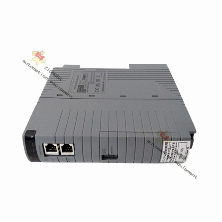
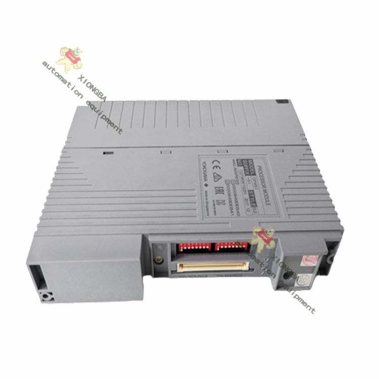
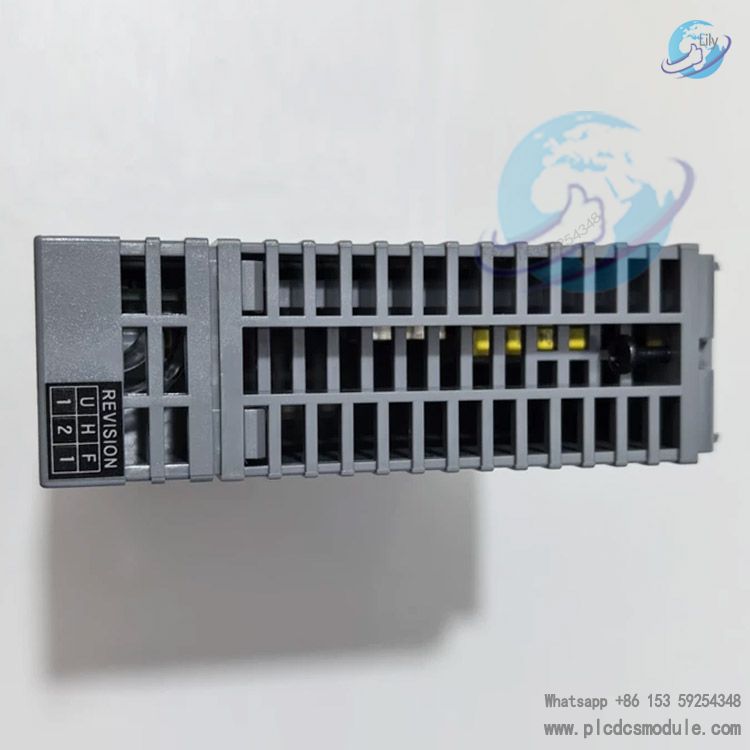
The AAI143‑S00 belongs to YOKOGAWA FIO‑series analog I/O modules. It measures 130 mm×107.5 mm×32.8 mm, fits standard FIO slot dimensions and supports hot‑swap maintenance, so replacement can be performed without system shutdown. Each channel is configured for 2‑wire or 4‑wire transmitter mode via onboard DIP jumpers, and power‑supply mode cannot be switched through software configuration.
Withstand voltage performance varies with matching cables. When self‑made MIL cables are adopted, withstand voltage depends on the cable’s own electrical parameters. The KS1 dedicated matching cable only provides 500 V AC withstand voltage, which shall be noted during model selection and construction.
The AAI143‑S00 is strictly prohibited from being connected in series with Zener safety barriers. For intrinsically safe explosion‑proof scenarios, isolated safety barriers must be used for explosion‑proof isolation instead of Zener barriers.
Application Fields
Process‑industry DCS projects including petrochemical, coal chemical, thermal power generation, water treatment, metallurgy and paper‑making. It collects 4‑20 mA analog signals output by pressure, flow and level transmitters to realize process variable monitoring, and is suitable for production facilities with heavy interference and high requirements for continuous system operation. The AAI143‑S00 is mostly used for ordinary analog acquisition points. Select the AAI143‑H‑series module if HART smart instrument diagnosis and reading are required.
Same‑brand Products Comparison
- AAI143‑S00: Module‑level isolation,16 AI,No HART,Basic isolated 4‑20 mA input, cost‑effective
- AAI143‑H00: Module‑level isolation,16 AI,With HART,Upgraded version of AAI143‑S00 with HART communication
- AAI141‑S00: Non‑isolated,16 AI,No HART,No isolation, low cost, for low‑interference scenarios
- AAI135‑S00: Channel‑to‑channel isolation,8 AI,No HART,8 channels with mutual channel isolation, complete fault independence
AAV144‑S00: Module‑level isolation,16 AI,No HART,Isolated voltage input module for 1‑5V /‑10~+10V signals

Related Matching Products
- Terminal Blocks & Adapters & Cables: ATA4S‑00, ATA4S‑10, ATA4D‑00, ATA4D‑10, ATK4A‑00, ACCC01, AEA4D
- Compatible Hardware Units: ANB10S, ANB10D, ANB11S, ANB11D, AFV30S/D, AFV40S/D, AFF50S/D
- Engineering Software: LHS5100 / LHMS5100 standard Builder configuration tool
FAQ
Q: Does the AAI143‑S00 module support HART protocol communication?
A: The AAI143‑S00 does not support HART. Select the AAI143‑H00 model for HART functions; the‑H suffix indicates built‑in HART modulation‑demodulation circuitry.
Q: Can the AAI143‑S00 be directly connected to Zener safety barriers for intrinsically safe explosion‑proof loops?
A: No. Official documentation prohibits pairing with Zener safety barriers. Isolated safety barriers shall be adopted for intrinsically safe applications.
Q: What are the main differences between AAI143‑S00 and AAI141‑S00?
A: The AAI143‑S00 features module‑level isolation for stronger anti‑interference performance. The AAI141‑S00 is a non‑isolated module with lower cost and no electrical isolation, intended for field sites with clean electromagnetic conditions.
Q: What are the installation requirements for dual‑redundant configuration of AAI143‑S00?
A: Two AAI143‑S00 modules of identical model must be inserted into adjacent odd and even slots of the same node unit, together with dual‑redundant terminal bases ATA4D‑00 / ATA4D‑10.
Q: How to troubleshoot insufficient loop voltage when a 2‑wire transmitter is connected to AAI143‑S00?
A: Confirm the channel DIP jumper is set to 2‑wire mode; calculate the minimum operating voltage of the transmitter and account for external cable voltage drop. The minimum terminal output of AAI143‑S00 is 19 V (20 mA). Excessive cable voltage drop will lead to insufficient instrument power supply.
Q: What is the input impedance of AAI143‑S00 after power‑off, and will it affect field transmitters?
A: Input impedance of the powered‑off module is ≥500 kΩ, which imposes almost no load impact on external transmitters. Powered‑off redundant standby modules will not pull down loop current.
Q: Can AAI143‑S00 be installed on the ANR10 ER bus node unit?
A: Hardware recognition is available, yet the ER bus node unit does not support HART‑related features. Since AAI143‑S00 has no HART function, only acquisition functions are available. Official recommendation prioritizes ESB / optical ESB node units.
Q: Is the 10 ms data refresh cycle of AAI143‑S00 per‑channel or per‑card?
A: 10 ms refers to the overall data update cycle for all 16 channels on the whole AAI143‑S00 card, and all channels refresh synchronously.
Notes
- When the KS1 dedicated cable is used with AAI143‑S00, input‑to‑system withstand voltage drops to 500 V AC. Corresponding withstand‑voltage specifications for selected cables shall be considered in engineering design.
- 2‑wire / 4‑wire transmitters require hardware DIP‑jumper setting for each channel; power‑supply mode cannot be modified via software.
- Dual‑redundant terminal bases must be adopted for redundant configuration; ordinary single‑channel terminal bases cannot be mixed‑used.
- Zener safety barriers are forbidden for intrinsically safe explosion‑proof loops; only isolated safety barriers are permitted.
- Route analog signal cables separately from high‑power power cables during installation to mitigate external electromagnetic interference.
- The module supports hot‑swap. Avoid plug‑and‑swap operations on critical acquisition loops vulnerable to process disturbance.
Product Tags
YOKOGAWA AAI143‑S00, AAI143‑S00, AAI143, Yokogawa FIO module, Analog Input Module, DCS Card, 4‑20 mA Isolated AI Module, Yokogawa FIO‑series Module, CENTUM VP I/O Module, 16‑channel isolated analog input module