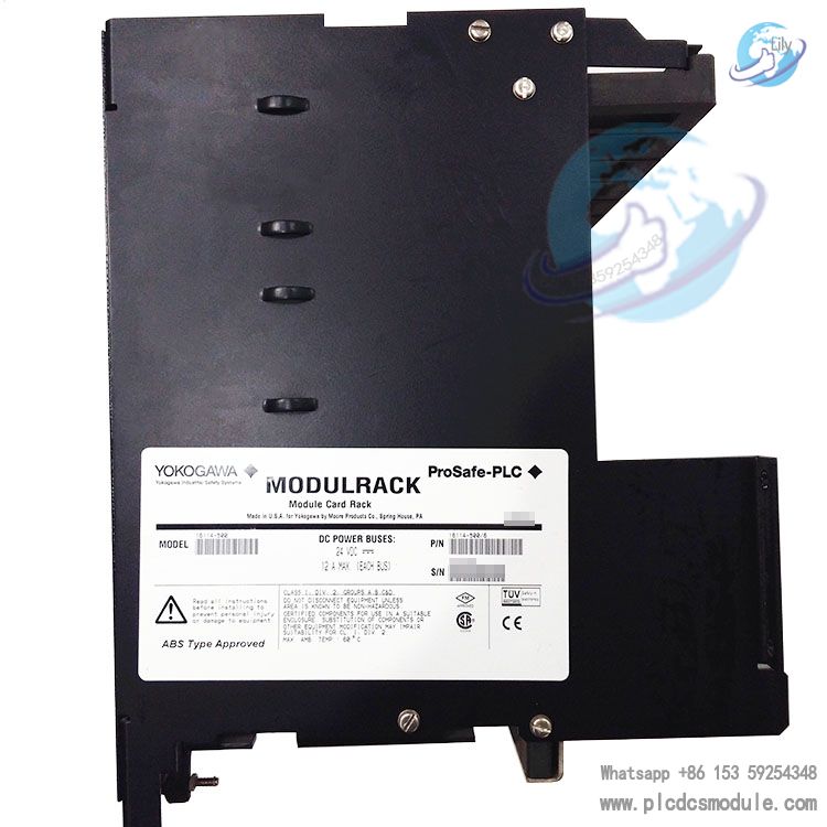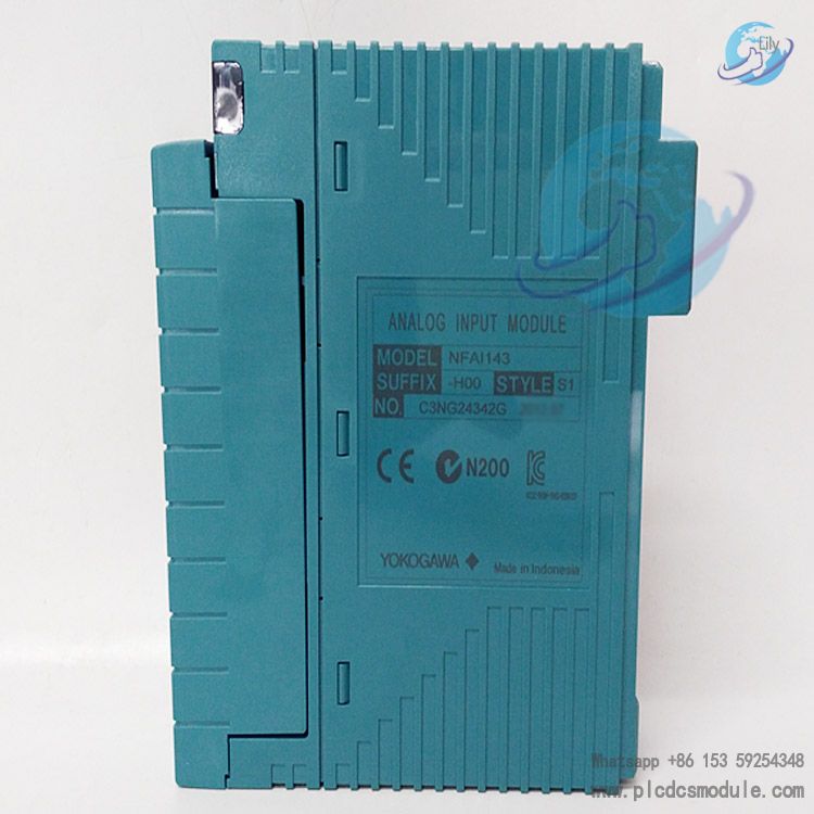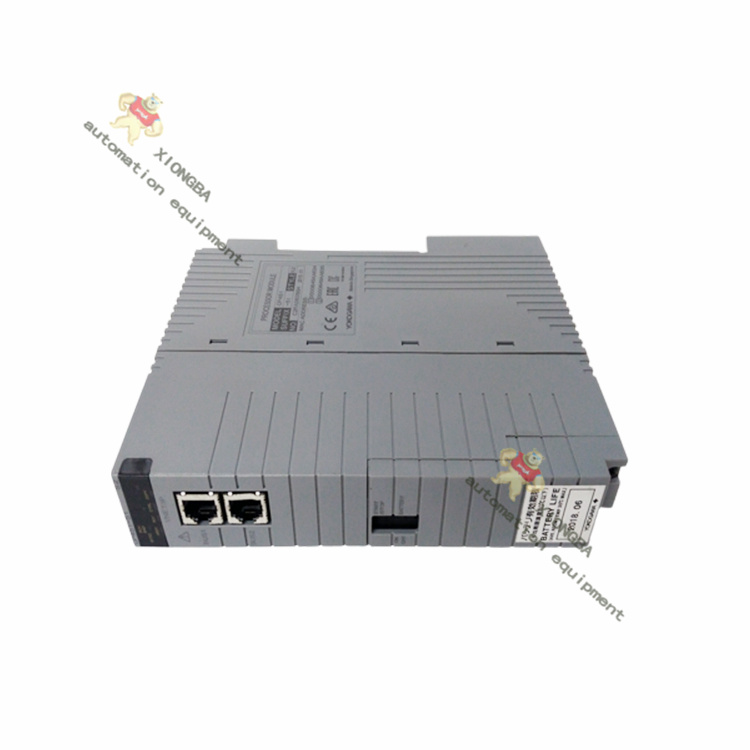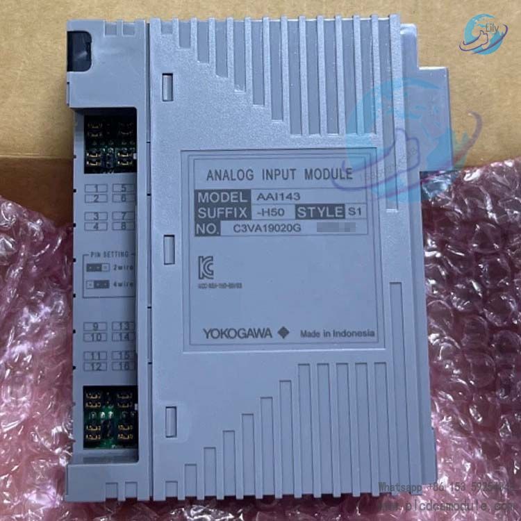
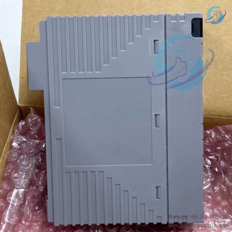
YOKOGAWA AAI143‑H50‑S1 Analog Input Module
Product Overview
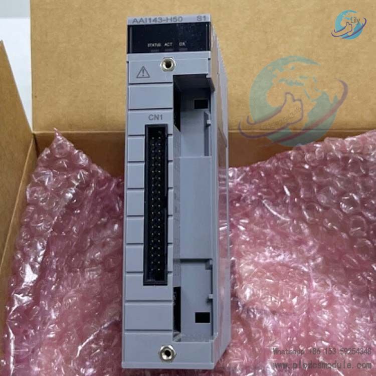
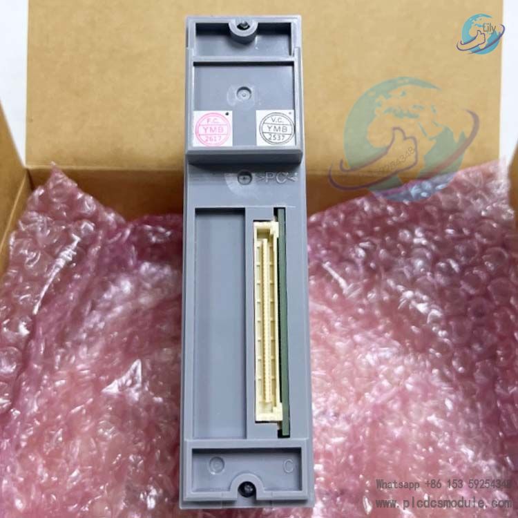
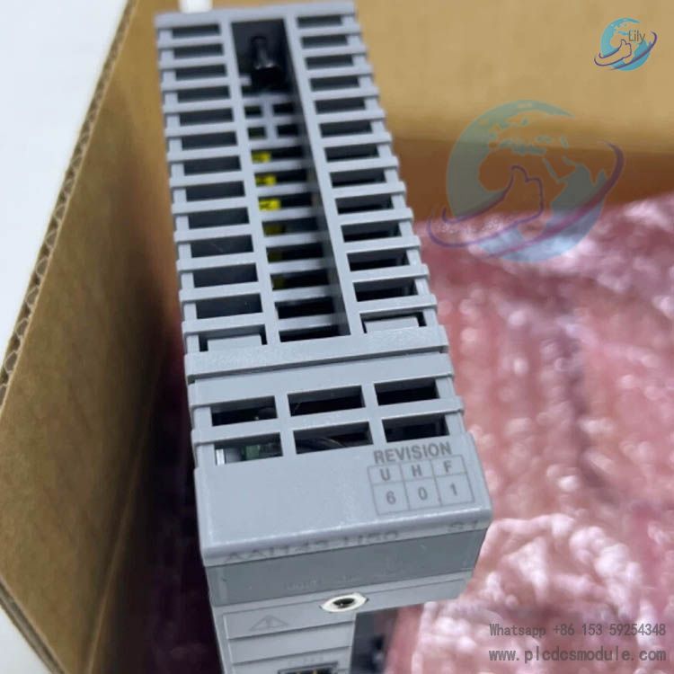
AAI143‑H50‑S1 is a 16-channel isolated 4‑20 mA analog input module for YOKOGAWA CENTUM VP DCS system. The module integrates HART communication function to collect 4‑20 mA DC current signals output from field 2-wire/4-wire transmitters, converts field analog signals into digital signals and uploads them to AFV30/AFV40 series FCS field control stations. It supports dual-module hardware redundancy. It is applied in process industries such as chemical, power, oil & gas, water treatment to collect process parameters including pressure, flow, liquid level, temperature, as well as read status and diagnostics of HART smart instruments.
Download

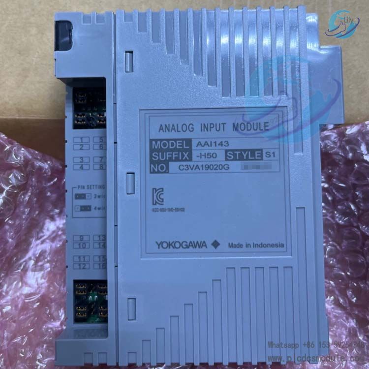
Model Suffix Decoding: AAI143‑H50‑S1
AAI143: Base model, 16-channel isolated 4‑20mA analog input module
‑H: Built-in HART modem, supports HART digital communication
5: No explosion-proof protection
0: Basic type, standard switching speed for redundancy
S1: Hardware version identifier
Main Technical Specifications
| Item | Parameter |
| Input Channels | 16 channels, isolation between field loop and system side, no isolation between channels |
| Input Signal | 4‑20 mA DC; each channel can be independently selected as 2‑wire / 4‑wire transmitter via jumper |
| Max. Allowable Input Current | 27mA |
| Withstand Voltage | Input to system side: 1500 V AC, 1min; reduced to 500 V AC when using dedicated KS cable |
| Input Resistance | Power-on: 290 Ω(20 mA)~450 Ω(4 mA); Power-off: ≥500 kΩ |
| Measurement Accuracy | ±16 μA |
| Data Update Cycle | 10 ms, step response time 100 ms |
| Temperature Drift | ±16 μA /10 ℃ |
| Transmitter Loop Power Supply | ≥14.8V @20 mA, ≤26.4V @0mA, output current limit 27 mA |
| HART Communication | Compatible with HART5/6/7; max. 16 HART devices per module; refresh cycle 1 s per device; max. 5 input devices per channel in multi-drop mode; 1200bps, FSK half-duplex communication |
| Power Consumption | Max 310 mA (5 VDC), 450 mA (24 VDC) |
| Weight | Approx. 0.20 kg |
| External Wiring | Clamp terminals, KS cable, MIL connector cable, multiple terminal board options available |
| Redundancy Capability | Supports dual-module redundancy. Two modules are installed in adjacent odd and even slots of the same node unit for redundant switching |
| Compatible FCS Controllers | AFV30S, AFV30D, AFV40S, AFV40D series field control stations |
Important Safety Note: This module must NOT be used with Zener safety barriers. For intrinsically safe explosion-proof applications, isolation safety barriers are mandatory.
Core Features
- System-side electrical isolation for anti-field interference
Electrical isolation between field signal loop and DCS system bus, 1500VAC dielectric strength. It suppresses ground loop and field common-mode interference, prevents field faults from damaging internal DCS hardware, suitable for industrial sites with multi-point grounding and strong electromagnetic interference. - Integrated HART smart instrument management
The module comes with built-in HART modem. Besides 4‑20mA analog process variables, it can directly read HART auxiliary variables, instrument diagnostics and device status. HART data can be used as process points for control logic operation via %Z terminal without extra HART adapter. HART communicator can be paralleled on-site to configure parameters and troubleshoot smart transmitters.
Note: HART multi-drop mode only supports input instruments; analog output value and HART Burst mode are not supported. When 16 HART devices are fully connected to one module, the total ESB bus refresh cycle is about 17s. - Flexible compatibility with transmitter types
Each channel can be set to 2-wire (module supplies loop power directly to transmitter) or 4-wire (external power for instrument) via hardware jumper, compatible with various industrial transmitters on site. - High-speed acquisition and stable operation
10ms high-speed data update, 100ms step response to meet acquisition requirements of conventional process control loops. Low temperature drift ensures measurement accuracy under wide working conditions. Hardware redundancy configuration enables bumpless switching for continuous production plants. - Various wiring accessories optional
Supports clamp terminal boards, KS dedicated cables, MIL connector cables. Optional standard terminal board, surge absorption terminal board, dual redundant terminal board, cable protection cover and other accessories for different cabinet construction solutions.
Order Option Codes
| Option Code | Accessory Description |
| /K4A00 | KS cable adapter, mating with AEA4D terminal board |
| /A4S00 | Single clamp analog terminal board |
| /A4S10 | Single clamp terminal board with surge absorption |
| /A4D00 | Dual redundant clamp terminal board |
| /A4D10 | Dual redundant clamp terminal board with surge absorption |
| /CCC01 | MIL cable connector protection cover |
Comparison with Non-isolated AAI141‑H
| Comparison Item | AAI143‑H (Isolated Type) | AAI141‑H (Non-isolated Type) |
| Isolation Feature | Electrical isolation between input and system side | No electrical isolation |
| Withstand Voltage | 1500V AC 1min (500V AC for KS cable) | N/A |
| Power-on Input Resistance | 290Ω@20mA ~450Ω@4mA | 400Ω@20mA ~1000Ω@4mA |
| Measurement Accuracy | ±16 μA | ±16 μA |
| Data Update Cycle | 10 ms | 10 ms |
| HART Function | Supported | Supported |
| Redundancy Configuration | Supports dual-module redundancy | Supports dual-module redundancy |
| Intrinsically Safe Requirement | Isolation barrier required, Zener barrier prohibited | Isolation barrier required, Zener barrier prohibited |
| Recommended Application | Large ground potential difference, heavy interference, DCS system protection required | Good field grounding, low interference, cost control priority |
Core Difference: AAI143‑H is equipped with electrical isolation. It is preferred for working conditions with ground loops and high power motor interference on site.
Installation & Commissioning Points
Hardware Installation & Redundancy: The module is installed in the slot of AFV30/AFV40 FCS node unit. For redundancy configuration, two AAI143‑H modules must be placed in adjacent odd and even slots. If KS dedicated cable is used for wiring, module isolation withstand voltage will drop from 1500VAC to 500VAC. Each channel selects 2‑wire / 4‑wire transmitter mode via hardware jumper.
Loop Voltage Verification for 2-wire Transmitters: Module input resistance varies dynamically with loop current: \(R_{in}=250\Omega+\frac{\text{Input protection circuit voltage drop}}{\text{Loop current}}\). During type selection and commissioning, verify: minimum operating voltage of transmitter ≤ module supply voltage − external cable voltage drop. Reserve design margin for cable voltage drop, otherwise the transmitter will work abnormally.
HART Communication Commissioning: Max. 16 HART devices per module, max. 5 input instruments per channel in multi-drop mode. HART variables are connected to function blocks via %Z software terminal. Communicator can be directly paralleled to field signal loop for communication. Hardware supports HART5/6/7 devices, while actual running protocol version is HART5.7.
Other Notes: Step response 100ms, not applicable for ultra-high speed acquisition scenarios. Redundancy modes include standard switching (suffix 0) and fast switching (suffix 6/F), select according to plant disturbance requirements. Input impedance ≥500kΩ when module power off.
System Data Flow
4‑20 mA analog signal superimposed with HART digital signal from field HART smart transmitter is connected to AAI143‑H module. The module writes analog measurement values and HART device variables into I/O image area. FCS field control station reads data from image area for regulatory control blocks and sequence logic operation. Data is uploaded to HIS human-machine interface for monitoring and alarm. ENG engineering station reads/writes parameters and implements diagnostics of field HART smart instruments via module channel.
Application Scenarios
- Petrochemical plants: signal acquisition of pressure, liquid level, flow transmitters and remote maintenance of smart HART instruments;
- Thermal power & hydropower industry: process analog monitoring of boiler, turbine auxiliary equipment;
- Long-distance pipelines, LNG plants;
- Metallurgy, pharmaceutical, water treatment and other process industries DCS analog signal acquisition.
FAQ
Q1: What is the core difference between AAI143‑H and AAI141‑H, and how to select for projects?
A: AAI143‑H is an input-system side isolated module, while AAI141‑H is non-isolated. When ground loops, large motor interference, multi-point grounding and big ground potential difference exist on site, AAI143‑H is preferred. If site grounding condition is good, electromagnetic interference is low and cost control is required, select AAI141‑H. Both share identical accuracy, HART function and update cycle.
Q2: Can AAI143‑H use Zener safety barrier for intrinsically safe explosion-proof loop?
A: No. Manual clearly states Zener safety barrier must not be used with this module. For intrinsically safe explosion-proof applications, isolation safety barrier must be adopted, otherwise loop abnormality and safety hazard may occur.
Q3: What are the mandatory slot requirements for dual redundancy configuration of modules?
A: Two AAI143‑H redundant modules must be installed in adjacent odd and even slots within the same node unit. Cross-node installation or slots separated by other modules are not allowed, otherwise redundancy switching function cannot work properly. Suffix 0 stands for standard switching; suffix 6/F for fast switching, select based on process disturbance requirements.
Q4: Will module isolation withstand voltage change when KS cable is used?
A: Yes. The module body input-system isolation withstand voltage is 1500V AC 1min. When KS dedicated cable is adopted, withstand voltage drops to 500V AC 1min. If MIL cable is used, withstand voltage depends on the electrical parameters of the cable itself, which needs to be derated in project design.
Q5: The 2-wire transmitter works unstably with occasional signal drop, which points need to be checked?
A: ① Verify loop voltage: ≥14.8V at 20mA of module. After subtracting cable voltage drop, the value must be higher than the minimum operating voltage of transmitter;
② Module input resistance is dynamic: \(R_{in}=250\Omega+\frac{\text{Input protection circuit voltage drop}}{\text{Loop current}}\). Lower current brings higher input resistance;
③ Confirm channel jumper is set to 2‑wire mode;
④ Check total loop current limit is 27mA and cannot exceed field instrument current.
Q6: What are the constraints for HART multi-drop mode?
A: ① Max. 5 HART input instruments per channel; valve output devices are not supported;
② Analog output value reading and HART Burst mode are not supported;
③ Max. 16 HART devices for one whole module;
④ When 16 devices are fully connected, ESB bus refresh cycle is about 17 seconds, refresh cycle 1s per single device.
Q7: Can HART5, HART6, HART7 smart instruments be directly connected to AAI143‑H?
A: Hardware is directly compatible with HART5/6/7 devices, but the internal running protocol of module is HART Revision5.7. Some unique new HART commands of higher version instruments cannot be executed. Basic variables and diagnostic information can be read normally. HART communicator can be directly paralleled on loop for commissioning.
Q8: The module has a 10ms data update cycle. Does it mean process signal response is 10ms?
A: No. 10ms is the internal data update cycle of the module, and step response time is 100ms. 10ms refers to module sampling and uploading rate. Step response includes input loop filtering, and it takes 100ms for DCS to read stable value after signal changes. This module is not suitable for ultra-high speed transient signal acquisition scenarios.