Bently Nevada 128240‑01 (for 3500/42M) Proximitor Seismic I/O Module
Product Overview
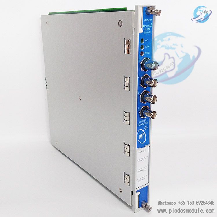
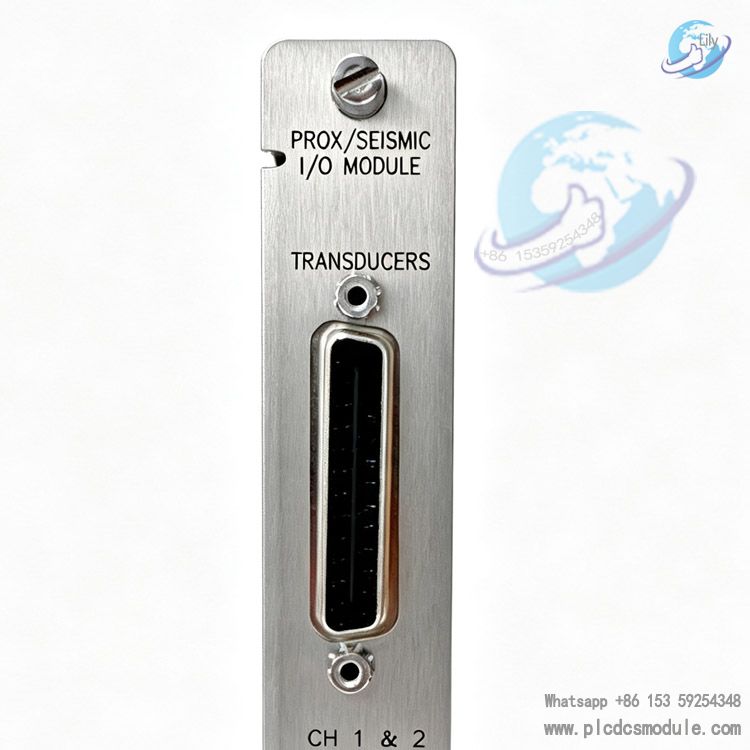
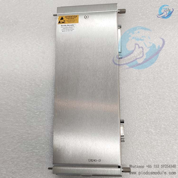
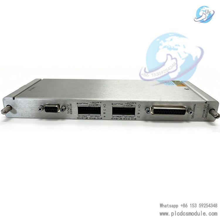
128240‑01 is a rear I/O module for the Bently Nevada (Baker Hughes) 3500 machinery protection system. Its full name is Prox/Seismic I/O Module with External Terminations. It works with the 3500/42M monitor front card and is installed in a full-height slot at the rear of the 3500 rack. It collects signals from field sensors and transmits them to the 3500/42M front card for calculation and processing, enabling rotating machinery vibration and shaft position monitoring and machinery protection.
Note: This module adopts external termination design. It cannot be matched with internal termination terminal blocks. External terminal blocks and dedicated cables need to be ordered separately for field wiring. It is not recommended for regular selection with Prox/Accel and Velomitor sensors, and is preferentially adapted to signal acquisition of Seismoprobe sensors.
System Function Positioning
Matched with the 3500/42M 4-channel monitor front card, the complete system achieves two core objectives:
- Equipment Protection: Continuously compares collected process parameters with configured alarm thresholds to trigger Alert and Danger alarm output interlocks.
- Status Feedback: Outputs key equipment data such as machinery vibration and shaft displacement to operation and maintenance personnel to support fault diagnosis.
The measurement functions supported by the 3500/42M front card (signals collected by the I/O module) include radial vibration REBAM, acceleration, differential expansion, eccentricity, shaft thrust position, shaft absolute vibration, velocity, and circular acceptance area. Channels are configured in pairs. One group of channels can be configured with up to 2 measurement functions at the same time. Multiple static measurement values can be configured for each channel. Warning thresholds can be set for all static values, and danger thresholds can be set for up to 2 static values. Alarm delay can be set via rack configuration software.
Signal and Interface Capabilities
- Channel Specification: 4-channel input, accepting signals from Proximitor sensors and Seismic sensors.
- Output Capabilities:
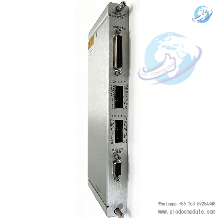
- Recorder Analog Output: 4‑20 mA, the output value is proportional to the full scale of the module. Short circuit of recorder output will not cause module failure. Load resistance: 0‑600Ω, output voltage range: 0~12Vdc.
- Buffered Sensor Output: Each channel on the front panel is equipped with a coaxial connector with short-circuit protection, output impedance 550Ω.
- External Termination Architecture: It relies on dedicated multi-core cables (25-core for sensor signal transmission, 9-core for recorder output transmission) to connect external terminal blocks. Field cables are not directly connected to the rack backplane, which facilitates wiring outside the cabinet and module replacement without modifying field cables.
Key Performance Indicators
1) Measurement Accuracy (excluding filtering error)
| Measurement Parameter | Accuracy Index |
| DC value, gap value | Full scale ±0.33%, typical maximum ±1% |
| 1X / 2X vector | Full scale ±0.33%, typical maximum ±1% |
| Smax amplitude | Max ±5% |
| Non-1X | <30000cpm: ±3%; >30000cpm: ±8.5% |
2) Frequency Response
Supports RMS, peak, peak-to-peak output modes, distinguishes single-channel and dual-channel enable modes. Supports filtering for acceleration, velocity, and REBAM bearing fault characteristics (BPFO rolling element outer race fault frequency, etc.). Built-in 4th-order high-pass, low-pass and Constant-Q notch filters. Minimum stopband attenuation: -34.9~‑57.7dB. Speed tracking filtering is supported, adapting to unit speed range from 60cpm to 60000cpm.
3) Physical Parameters
- Installation Position: 1 full-height slot at the rear of the 3500 rack.
- Dimension (H × W × D): 241.3 mm ×24.4 mm ×99.1 mm.
- Weight: 0.20 kg.
- Power Supply: Powered by 24Vdc from 3500 rack backplane, power consumption 1.09W.
- Operating Environment: Matched with the whole system, operating temperature -30℃~+65℃, maximum humidity 95% non-condensing.
Software & Firmware Compatibility
To fully utilize all functions of the module, matching specified versions of software/firmware are required:
- The 3500 rack configuration software and 3500/42M front card firmware need to match corresponding versions.
- Supports DM2000 host software to read monitoring data.
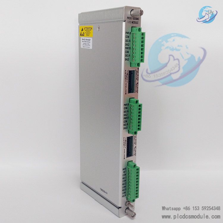
Reference Spare Part Numbers: 128240‑01 refers to the I/O module body. External terminal blocks and dedicated cables need to be ordered separately. Comparison with the same series: 128229‑01 is the internal termination version I/O module. Field cables are directly connected to the backplane terminals of the module, and it cannot share terminal accessories with this external termination 128240‑01.
Certifications & Compliance
The complete system meets CE EMC (EN 61000‑6‑2, EN 61000‑6‑4), low voltage safety standard EN61010‑1 and RoHS. It supports ABS, DNV‑GL marine and offshore platform certifications. It can be used with Bently isolation barriers to meet ATEX/IECEx and cNRTLus requirements for hazardous area applications.
Application Scenarios
Widely used in TSI (Turbine Supervisory Instrumentation) systems for rotating machinery such as steam turbines, compressors, fans and pumps to monitor shaft vibration, shaft displacement and differential expansion, and realize equipment over-limit alarm and interlock protection. The external termination version is more suitable for centralized wiring outside the cabinet. Hot-swap maintenance of the module does not require disconnecting field sensor cables.
Brief Comparison with 128229‑01
| Model | Terminal Type | Wiring Features |
| 128240‑01 | External Terminations | The rack connects external terminal blocks via cables, field cables are connected to terminal blocks. Field cables remain untouched during module maintenance. |
| 128229‑01 | Internal Terminations | Field cables are directly crimped to the backplane terminals of the I/O module. Field wiring needs to be removed when replacing the module. |
Important Note: The 128240‑01 external termination I/O module cannot use terminal blocks for internal termination. Corresponding external terminal blocks and connecting cables need to be ordered synchronously.
FAQ
Q1: What is 128240‑01? What is its relationship with 3500/42M?
A: 128240‑01 is a rear I/O module installed in the rear slot of the 3500 rack. 3500/42M is the front monitor card. They must be used in pairs. The I/O module receives signals from field sensors and sends them to the 3500/42M card for measurement calculation and alarm logic processing.
Q2: What are the differences between 128240‑01 and 128229‑01? Can they be interchanged?
A:
128240‑01: External Terminations. External terminal blocks and dedicated connecting cables are required between the module and field cables.
128229‑01: Internal Terminations. Field cables are directly connected to the backplane terminals of the I/O module. Their hardware shapes are different and terminal accessories cannot be mixed. Only rack slots are compatible. Direct replacement is not allowed, and the whole set of wiring accessories needs to be modified for replacement.
Q3: What sensors does 128240‑01 support?
A: It supports Proximitor eddy current sensors and Seismoprobe seismic sensors.
Document note: Although hardware can connect Prox/Accel and Velomitor, it is not recommended. If a large number of Velomitor sensors are to be used, 140482‑01 Prox/Velom external termination I/O module is preferred.
Q4: How many rack slots does 128240‑01 occupy?
A: The I/O module occupies 1 full-height slot at the rear of the rack; the 3500/42M monitor card occupies 1 full-height slot at the front of the rack.
Q5: Does spare part number 128240‑01 include the 3500/42M front card?
A: No. 128240‑01 is only the rear I/O module. Spare part number for 3500/42M monitor card: 176449‑02.
Q6: What are the software and firmware version requirements for using 128240‑01?
A: It depends on the functions enabled by 3500/42M:
Basic functions: 3500‑01 software V2.50 and above;
Shaft Absolute enabled: Higher version firmware and software required;
REBAM enabled: 3500‑01 V3.20, module firmware 2.10, DM2000 V3.30.
Configuration uses 3500 Rack Configuration Software.
Q7: Is 128240‑01 itself an explosion-proof isolation barrier? Can it be directly connected to sensors in hazardous areas?
A: It is not an intrinsic safety barrier itself. For explosion-proof hazardous area applications, I/O modules with built-in isolation barriers (such as 135489‑xx series) should be selected. 128240‑01 is a non-explosion-proof I/O module. An external third-party safety barrier is required for hazardous area applications.
Q8: What is the operating temperature range?
A: When matched with ordinary I/O modules for the whole system: -30℃ ~ +65℃; maximum humidity 95% non-condensing.
Q9: For external termination modules, do field sensor wires need to be disconnected when replacing the I/O module?
A: No. Field sensor cables are connected to external terminal blocks outside the cabinet. Only the rack-side cable needs to be plugged/unplugged when replacing the module, and field sensor wiring remains unchanged. This is the biggest advantage of the external termination solution.
Q10: Can 128240‑01 be directly inserted into the rack without external terminal blocks?
A: No. The signal loop cannot be completed and the system cannot collect sensor signals normally.
Q11: What speed limits apply to the REBAM function?
A: The effective speed of REBAM depends on the configured nominal shaft speed, refer to Table 4 in the manual. It is also limited by the number of rolling elements of the bearing. REBAM must be connected to a valid speed signal, and the speed tracking filtering function relies on speed input.
Q12: Can 128240‑01 perform shaft absolute vibration measurement?
A: Hardware does not support it. Shaft absolute measurement requires dedicated Shaft Absolute I/O modules (138708‑01 internal termination /138700‑01 external termination).