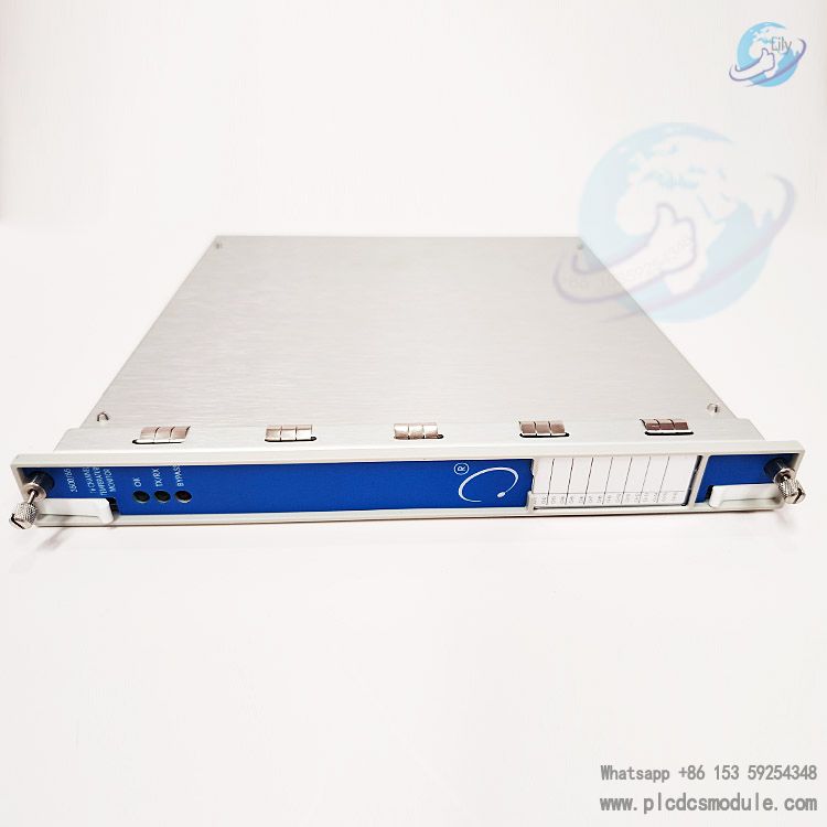
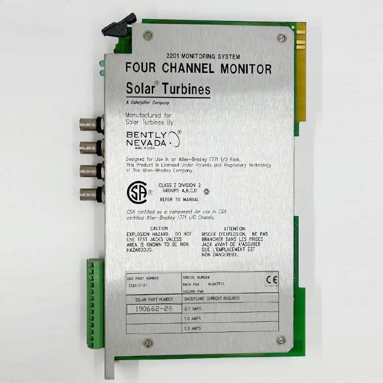
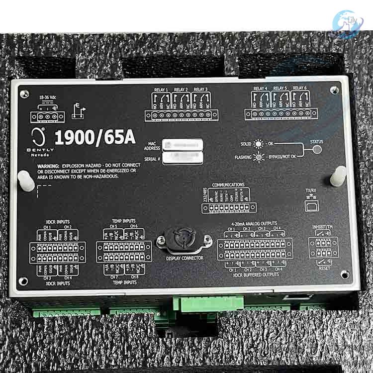
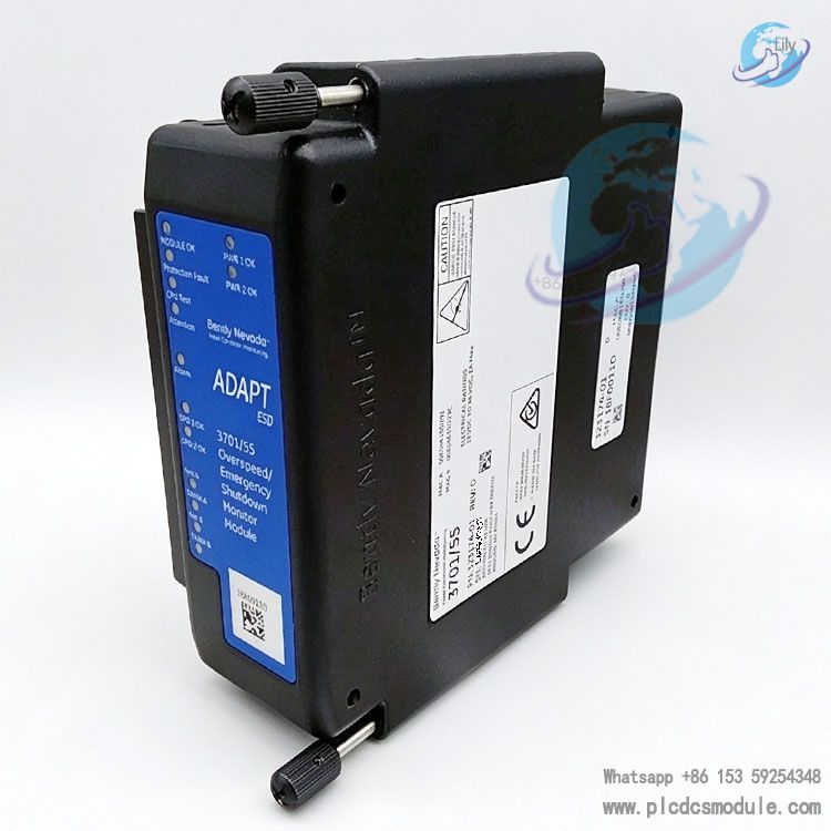
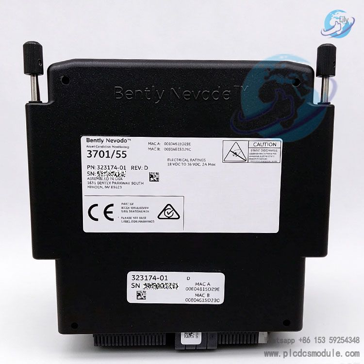
Bently Nevada 323174‑01 ADAPT ESD CPU Module
Product Overview
323174‑01 is the core CPU processing module for the 3701/55 ADAPT ESD Emergency Shutdown System, manufactured by Bently Nevada, a Baker Hughes company. Designed for triple-modular redundant safety protection of rotating machinery, the complete system is a SIL3 rated safety PLC integrating overspeed detection and emergency shutdown logic processing.
Product Positioning
The 323174‑01 is a high-performance processing CPU module. A single 3701/55 ESD chassis requires three of these CPUs to form a TMR (Triple Modular Redundant) 2oo3 voting architecture. It is specially deployed for overspeed protection and emergency shutdown control of critical rotating assets including steam turbines, gas turbines, hydro turbines and expanders.
The full ADAPT‑ESD is a compact, standalone safety shutdown unit with graphical logic configuration software and comprehensive self-diagnostics. Three CPUs process all input signals in parallel, execute safety logic calculations and send output commands to drive relay modules (323073‑01) to trigger shutdown actions. Online firmware upgrade is supported without removing modules from the chassis to update embedded programs.
Core Hardware Functions
1. Signal Input Processing
Speed Input Channels: Each 323174‑01 CPU features 2 independent speed channels. With three CPUs installed in the system, a total of 6 speed acquisition channels are available. It accepts two types of speed sensors: proximity probes and magnetic pickup (MPU) sensors.
- Proximity probe: Frequency range 3Hz‑10kHz, minimum input amplitude 1Vpp
- Magnetic pickup MPU: Frequency range 2Hz‑20kHz, minimum input amplitude 1.0Vpp
- Maximum speed measurement range: 120000rpm
- Pulses per revolution (EPR): 1‑999 configurable
- Speed measurement accuracy: ±0.1RPM below 100RPM; ±1RPM within 10000RPM; ±0.01% of full scale above 10000RPM
Digital & Analog Inputs: All three CPUs synchronously process all 32 DI discrete inputs of the rack. 12 channels can be software-configured as 4‑20mA analog inputs; the remaining 20 channels support discrete signals only. 4‑20mA analog input withstands fault voltage up to ±40V.
4‑20mA Recorder Output: Each CPU includes 2 isolated 4‑20mA speed transmission outputs. Full scale can be set via software, maximum loop impedance 750Ω, maximum error 0.1mA for speed data transmission to recorders or DCS systems.
2. Logic Processing Performance
- Maximum logic blocks: 500
- Supported function blocks: AND/OR/XOR, RS flip-flops, timers, M-out-of-N voting, inverters
- Nominal input-to-output logic decision time: 2ms
- Relay switching time: 8ms; maximum time from fault detection to relay status change: 30ms, ensuring millisecond-level shutdown protection upon fault occurrence
- Configurable voting modes: 1oo1 standalone mode or system-level 2oo3 triple modular redundant voting. The safety recommended configuration is normally energized (trip on loss of power) to avoid loss of machine protection during power failure.
3. Network Communication
- Dual redundant Ethernet ports per CPU, total 6 network ports for the complete rack
- Communication speed: 10/100Mbps, TCP/IP protocol
- Supports DHCP dynamic IP and static IP; NTP time synchronization
- Recommended deployment: Connect the first CPU port to Subnet A and the second port to an independent Subnet B for redundant communication links
- Configuration software: Bently Nevada Monitor Configuration, compatible with Windows 7 (32/64-bit). Password protection for modification access to configure logic, overspeed thresholds and relay modes.
4. Front Panel LED Status Indicators
LED indicators enable fast on-site troubleshooting:
| LED | Status Definition |
|---|---|
| Module OK (Green) | Solid ON = Module healthy; OFF = Self-test failure; 2Hz Flash = Unconfigured |
| CPU Test LED | OFF = Run mode; 2Hz Flash = Test mode active |
| CPU Attention (Green) | New event logged; OFF = No pending events |
| CPU Alarm | OFF = No alarm; 2Hz Flash = Single channel alarm; 5Hz Flash = Multi-channel alarm |
| Speed LED (Green) | Solid ON = Speed signal normal; OFF = No signal; 2Hz Flash = Abnormal speed signal |
| Net, TX/RX | Network link and data transmission/reception status |
| PWR | Power supply indicator |
Physical & Environmental Specifications
Mechanical Dimensions & Weight (Single 323174‑01 CPU Module)
- Dimensions: 15.8 × 6.1 × 15.8 cm (6.2 ×2.4 ×6.2 inches)
- Weight: 1.2kg
Complete 3701/55 ESD Unit
- Dimensions: 25.4×30.48×18.0cm
- Weight: 8.8kg
- Mounting: Vertical installation required, power terminals routed horizontally. Minimum cabinet depth requirement: 9 inches for adequate heat dissipation.
Environmental Ratings
- Operating temperature: −30℃ ~ +65℃
- Storage temperature: −45℃ ~ +85℃
- Humidity: 0‑95% non-condensing
- Vibration: Complies with IEC 60068‑1
- Shock: Complies with IEC 60068‑2 (15g@11ms)
Power Supply
- System input power: 18‑36VDC
- Typical total power consumption: 24W; maximum 35W
- CPU powered via rack backplane
Safety Certifications
- Functional Safety: IEC61508 SIL3 certified
- Machinery Directive: 2006/42/EC
- CSA North American safety certification; Intrinsic safety rating: Class1 Div2 / Zone2
- ATEX / IECEx II3G Ex nA nC IIC T4 Gc
- CE (LVD Low Voltage Directive, EMC Electromagnetic Compatibility)
- ABS marine classification approval; RoHS compliant
Note: The unit cannot be mounted directly in Zone0 or Zone1 hazardous areas. Isolation barriers or Zener safety barriers are required to interface sensors installed in Zone0/Zone1.
Compatible Hardware List
| Part Number | Description | Remarks |
|---|---|---|
| 323174‑01 | ADAPT ESD CPU Module | This product; 3 units required per rack |
| 323073‑01 | Standard Relay Output Module | 3 units per rack, 5 SPDT relay contacts per module; 2oo3 voting configurable |
| 323073‑02 | Gold-plated Contact Relay Module | No explosion protection certification |
| 289761‑01 | Terminal Base Assembly | Mounting base for CPU and relay modules |
| 103M1345‑01 | Configuration Software CD | Bently Monitor Configuration software |
Application Industries
- Power Generation: Steam turbine generator sets, hydro turbine generator sets for overspeed protection and ETS emergency shutdown
- Oil & Gas: Gas turbines, expanders and large process compressors in refineries and petrochemical plants
- Coal Chemical: Critical rotating machinery, compliant with API‑670 machinery protection standard
Working Architecture Overview
Three 323174‑01 CPUs receive all DI/AI signals together with their individual 2-channel speed inputs, independently execute user-defined safety logic and send outputs to 3 relay modules.
Six relay channels support 2oo3 voting mode: a shutdown command will only be triggered when at least 2 CPUs assert trip signals to prevent false trips caused by single CPU faults. 1oo1 standalone mode is also available where trip signals from any single CPU actuate the corresponding relay.
Normally energized trip mode is recommended. If rack power is lost, relays will directly trigger shutdown to avoid operation without machine protection.
Frequently Asked Questions
Q1: Can the 323174‑01 module operate independently as a single unit?
A: No. This module is the CPU processing unit for the 3701/55 ADAPT ESD system. Three 323174‑01 modules must be installed to build the TMR triple redundant architecture to achieve full SIL3 safety functions. A single module cannot perform 2oo3 voting logic and cannot serve as a standalone protection device.
Q2: How many speed input channels per 323174‑01? What is the total speed channel count of the complete system?
A: Each CPU module has 2 independent speed input channels. With three CPUs installed, the full system provides 6 speed channels. It supports both proximity probes and magnetic MPU speed sensors, configurable pulses per revolution (EPR) from 1‑999 and maximum measurable speed up to 120000rpm.
Q3: What is the logic response time and maximum supported logic blocks?
A: Without timer delays, nominal input-to-output logic decision time is 2ms. Relay switching time is 8ms, maximum time from fault detection to relay status update is 30ms. The system supports up to 500 logic blocks including AND, OR, XOR, RS flip-flops, timers and M-out-of-N voting functions.
Q4: Does firmware upgrade require removing the 323174‑01 module from the rack?
A: No. This CPU supports online firmware upgrade. Module removal is not required. Firmware update can be completed via Ethernet connection using the configuration software to reduce downtime for maintenance.
Q5: How to configure the CPU Ethernet ports and what are the purposes of dual ports?
A: Each CPU has dual Ethernet ports, 6 network ports total for the whole system. Static IP and DHCP are supported with NTP time synchronization. Best practice: connect the first port to primary subnet and the second port to a separate secondary subnet for redundant communication links. Placing both ports on the same network segment is not recommended. The configuration software connects to modules over TCP/IP Ethernet.
Q6: What are the relay contact limitations for SIL3 applications with the 323174‑01 system?
A: Under SIL3 safety mode, relay contact current ≤1A AC/DC; AC power ≤250VA, DC power ≤150W, maximum contact voltage 250VAC /250VDC. Unused terminals on the base must remain unconnected. All requirements in the safety manual must be strictly followed.
Q7: What fault condition is indicated when the Module OK LED flashes at 2Hz?
A: A 2Hz flashing Module OK LED indicates the CPU module has not been loaded with configuration. Use Monitor Configuration software to download the valid project configuration to the module. After successful download, the green Module OK LED will stay solid ON.
Q8: Can the CPU module be mounted directly in Zone0/Zone1 hazardous areas? How to connect field sensors?
A: The 3701/55 system (including 323174‑01 CPU) is rated for Class I Div2 / Zone2 installation only. Direct installation in Zone0 and Zone1 is prohibited. If speed sensors are located in Zone0 or Zone1, Zener barriers or galvanic isolation barriers must be used. Ground jumpers on the terminal base can be removed to match grounding requirements for Zener barriers.