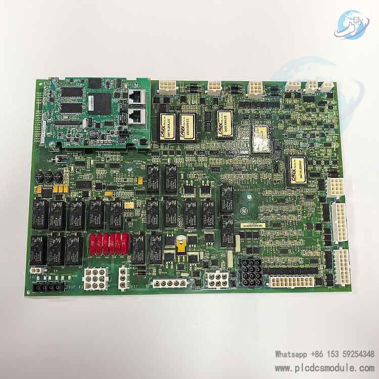


GE IS420YDOAS1B (YDOA) I/O Pack Module
Product Information
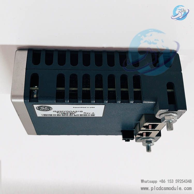
IS420YDOAS1B is a relay discrete output I/O Pack for the GE Mark VIe / Mark VIeS functional safety system. As the core component of the safety relay output module, it forms a complete relay output assembly together with its matching terminal board. It is widely deployed in gas turbines, steam turbines and combined-cycle power plants for ESD emergency shutdown, BMS burner management, interlock protection, solenoid valve / contactor driving and other SIS safety instrumented loops, compliant with IEC 61508 SIL2 / SIL3 safety requirements.
This I/O Pack has no built-in wiring terminals and must be mounted onto a compatible terminal board for operation. It supports Simplex, Dual and TMR (2-out-of-3) architectures. It communicates with UCSC controllers over the IONet industrial Ethernet, with full coil status feedback, output diagnostics and SOE sequence-of-event logging capabilities.
Key Specifications
| Item | Parameter |
|---|---|
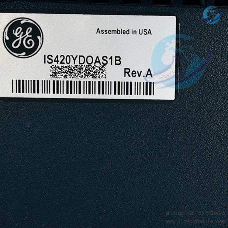
| Model | IS420YDOAS1B (Short Name: YDOA) |
| Function | Discrete Relay Output I/O Pack |
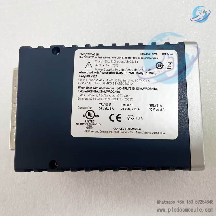
| Control Power Supply | 24‑28 V DC, Max. Power Consumption 19.8 W (including relay coil drive) |
| Safety Certifications | IEC 61508 SIL2/SIL3; Class1 Div2 / ATEX Zone2 Explosion-proof; G3 Corrosion Resistance |
| Operating Temperature | -40℃ ~ +70℃; Storage Temperature: -40℃ ~ +85℃ |
| Housing | Aluminum alloy housing with status LED indicators |
| Communication Interface | IONet Ethernet, supports Simplex/Dual/TMR I/O Network |
| Diagnostic Features | Power-on self-test, I/O pack hardware health monitoring, output command-feedback comparison, undervoltage detection, fuse fault detection, terminal board model verification |
| Mounting | Snap-on installation onto matching DIN-rail mounted terminal boards |
| Redundancy Modes | Simplex (1 unit), TMR (3 I/O packs with TMR terminal board) |
Note: The actual output contact rating and contact type (Form‑C/Form‑A/Form‑B) are determined by the paired terminal board, not the I/O pack itself.
Core Advantages
Complete Functional Safety Qualifications
Certified to IEC 61508 functional safety standards. SIL2 / SIL3 safety level can be achieved when paired with the correct terminal board. It also carries Class1 Div2, ATEX Zone2 explosion-proof and G3 corrosion certifications, suitable for hazardous process areas in power stations and chemical plants.
Flexible Redundancy to Reduce Project & Spare Parts Cost
The same I/O hardware supports Simplex, Dual and TMR redundancy configurations simply by changing the terminal board. The IONet network can also be set to different redundancy grades to match SIL requirements, minimizing spare part SKUs and inventory investment.
Full Closed-Loop Diagnostics to Prevent Latent Failures
It supports power-on self-test, output command-feedback comparison, coil monitoring, fuse fault detection, wetting power loss alarm and terminal board validation, alongside millisecond-level SOE event logging. Open/short circuit of solenoid coils can be detected in advance to identify actuator risks.
Modular Split Design Supports TMR Online Hot Maintenance
The I/O pack is separated from the wiring terminal board. In TMR mode, a single faulty pack can be hot-swapped without shutdown. The system degrades to maintain safety functions, with no on-site wiring changes and reduced maintenance downtime.
IONet Distributed Ethernet I/O Architecture
Backplane-independent design allows both centralized and distributed I/O layout. Modules can be installed close to field equipment to save long-distance field cabling.
Wide Hardware Compatibility & Diverse Load Options
Compatible with the full SRLY and TRLY terminal board series as well as WRO wetting sub-boards. It supports Form‑A/B/C contact types for standard relay output, coil monitoring and solenoid valve integrity checking, covering solenoid valves, contactors and other loads.
High Reliability for Harsh Industrial Environments
Wide operating temperature range of -40℃~+70℃, aluminum housing and G3 corrosion resistance for high-humidity, corrosive industrial sites. It features reverse power polarity protection and inrush current suppression for hot-swap operations.
Deep Platform Integration & Secure Networking
Natively integrated with the Mark VIeS platform. ToolboxST handles configuration, diagnostics and event logging in one unified environment. It supports cause-and-effect matrices and FBD safety logic, holds Achilles Level‑1 cybersecurity certification, and enables seamless integration with third-party DCS via OPC-UA and Modbus.
Compatible Accessories
1. Matching Terminal Boards (Mandatory, defines channel specification and redundancy)
IS410SRLYS2A (SRLY): Simplex relay output terminal board; 12-channel Form‑C relay outputs; 48 field wiring terminals; only works with one IS420YDOAS1B. WRO sub-boards can be added for contact wetting and fuse protection.
IS410TRLYS1B (TRLY): Supports Simplex / TMR; 12-channel Form‑C relays with coil sensing monitoring.
IS410TRLYS1D: Supports Simplex / TMR; full solenoid loop integrity checking, capable of measuring solenoid coil resistance to detect open/short circuits.
IS410TRLYS1F / IS410TRLYS2F: TMR dedicated. S1F: 12-channel normally open Form‑A; S2F: 12-channel normally closed Form‑B. The terminal board provides hardware 2oo3 voting output.
2. Optional Contact Wetting / Fuse Sub-boards (for SRLYS2A)
IS400WROBH1A: Contact wetting sub-board
IS400WROFH1A: Solenoid-specific wetting + fuse sub-board
IS400WROGH1A: Wetting sub-board
3. Controllers, Network & Power Accessories
IS420UCSCS2A (UCSC Safety Controller): Mark VIeS safety controller that executes safety logic and sends output commands over IONet, supporting Simplex/Dual/TMR redundancy.
IS420ESWAHxxA / IS420ESWBHxxA IONet Industrial Switch: I/O network switch for data exchange between I/O packs and controllers.
PDM Power Distribution Module (e.g. IS410JPDGH1A): Supplies 28V DC control power and 24/48V contact wetting power with power fault diagnostics.
ToolboxST Software: Used for system configuration, logic programming, diagnostic review and firmware download.
4. Spare Parts
Module Cover: 151X1202YE04PP05BL (for SRLY), 151X1202YE08PP18BL (for TRLY)
Maintenance Instructions
1. Installation Notes
This is an ESD-sensitive component. Always wear an anti-static wrist strap during handling and avoid direct contact with circuit board metal contacts. The I/O pack snaps onto the terminal board; confirm latches are fully locked. TMR setups require three identical IS420YDOAS1B packs installed on one TRLY terminal board. Use a PDM module to supply stable 24‑28 V DC control power. Do not connect directly to unstable field power sources. Surge suppression must be fitted for field solenoid valves and inductive loads to prevent reverse voltage damage to relay contacts and the I/O pack. For explosion hazardous locations, follow the GEH‑6861 installation guide for hazardous area equipment.
2. Periodic Routine Maintenance
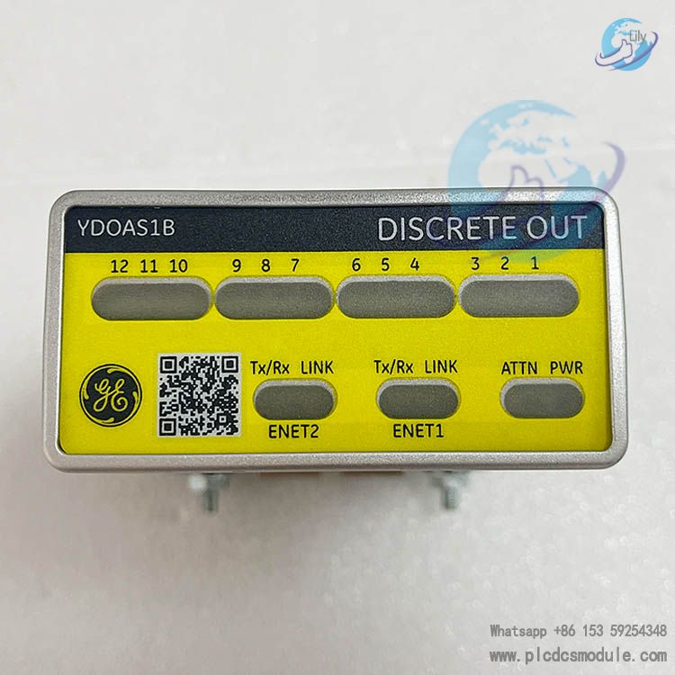
Inspect every 6 months: visual check for overheating, discoloration or burn marks; verify tight terminal connections and normal LED status; confirm secure DIN rail mounting. Use ToolboxST / AlarmViewer to check module diagnostic alarms and SOE event logs; export fault records regularly. Interpret the ATTN indicator: steady green flash = online normal; steady red or red flashing = fault condition. Perform periodic on-load testing of relay output channels per site SIS test schedules to verify output action and feedback consistency. Maintain cabinet ambient conditions within -40~+70℃, no condensation and corrosive gases to satisfy G3 requirements.
3. Online Replacement (TMR Redundancy Mode)
Hot-swap of a single I/O pack is permitted under TMR architecture. The system degrades to 1oo2 while retaining safety functionality. Confirm LED status returns to normal and alarms clear after replacement. Simplex configurations will lose output power during I/O pack replacement. Process isolation or shutdown is mandatory before service.
4. Firmware
I/O pack firmware is downloaded together with the ToolboxST project. Mismatched firmware versions must never be used; version incompatibility triggers hardware mismatch faults.