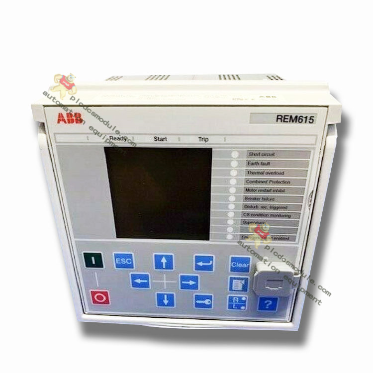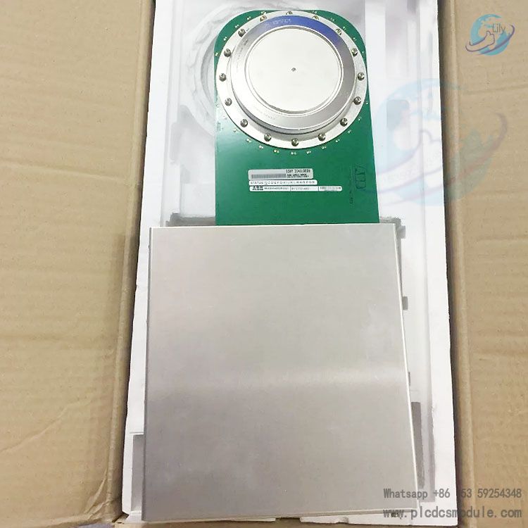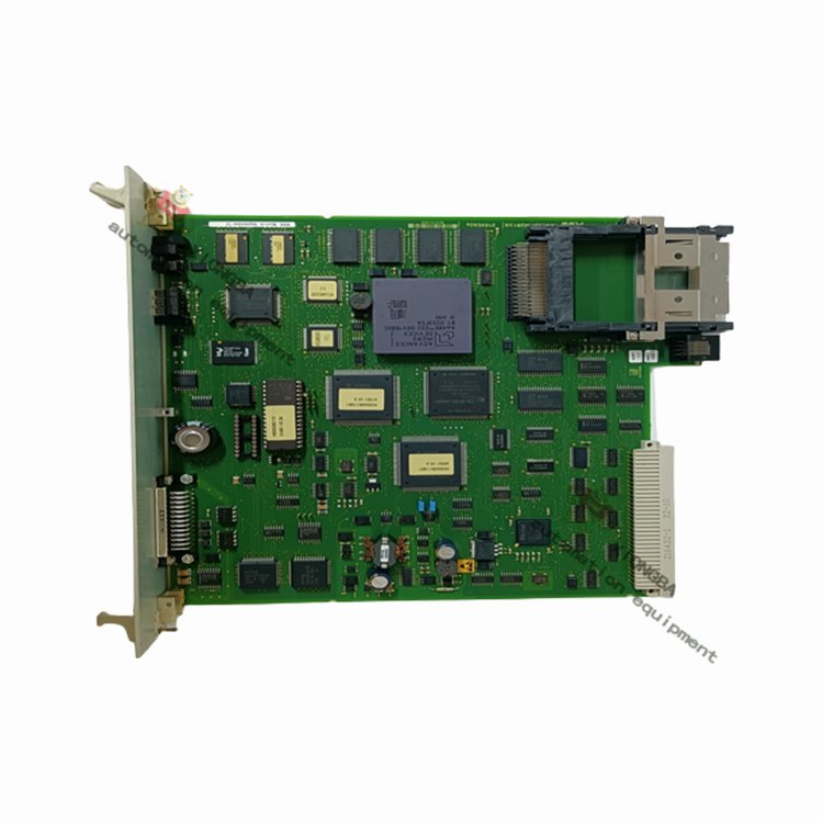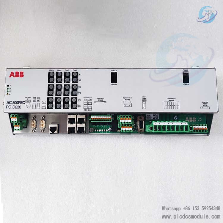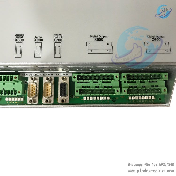
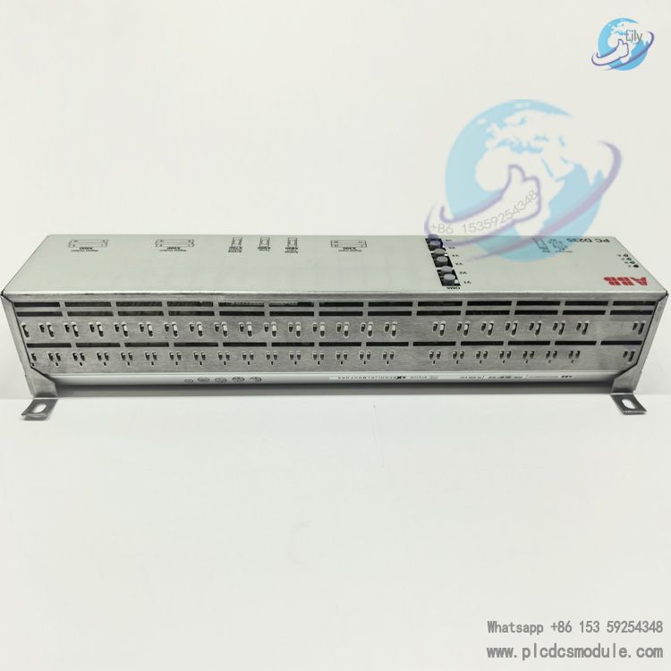
ABB PCD235A101 3BHE032025R0101 CIO-FU Integrated Input/Output Module UNITROL 6000
Product Overview
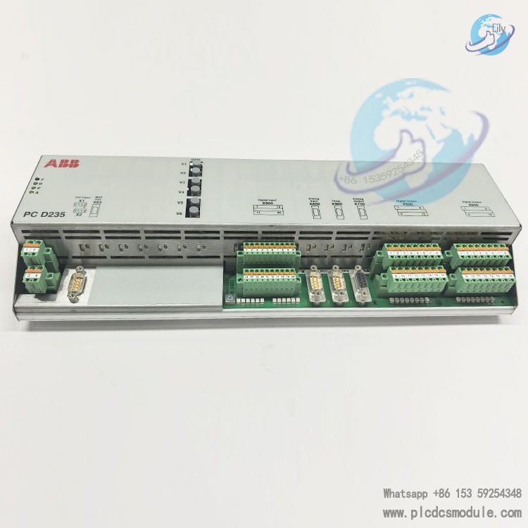
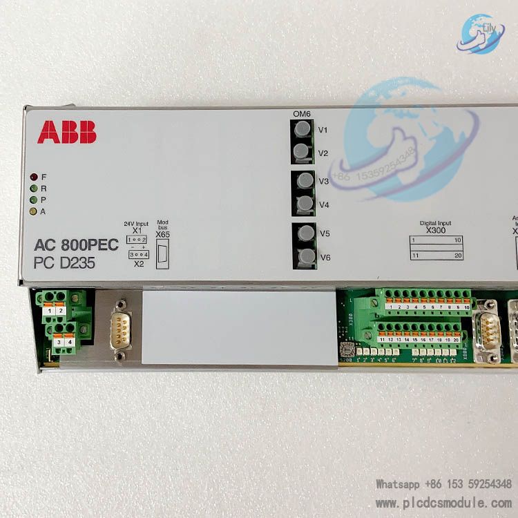
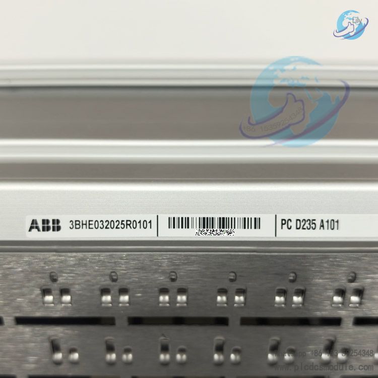
PC D235 A101 (also marked PCD235A101, part number 3BHE032025R0101), full name AC800PEC CIO‑FU Integrated Input/Output Module, is developed based on the AC 800PEC control hardware platform. It serves as the core I/O interface board for the UNITROL®6000 excitation control system and is a critical spare part within the ABB UNITROL 6000 excitation spare parts list.
The module consists of four internal components: FPGA control unit, application interface board, power supply unit and optical fiber communication module. It features an independent hardware watchdog and 4 system status LED indicators. The device address can be set from 0 to 15. The hardware supports hardware hot redundancy for all system interfaces by deploying two PC D235 A101 modules, significantly improving the operational reliability of generator excitation systems.
This product is an interface I/O board, not a CPU main control unit. It must work with the UNITROL6000 series main control board. The board firmware logic is customized for excitation scenarios and cannot be directly used as a general-purpose PLC I/O module.
Hardware I/O Resource Configuration
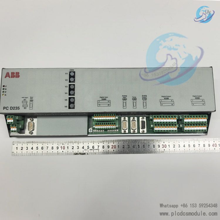
Digital Output (Relay): 16 relay outputs. Contact rating: 240VAC/2A AC, 250VDC/0.3A DC, isolation withstand voltage 500Vrms. Divided into 2 groups, 8 channels per group.
Digital Control Input: 12 channels of 24V/48V digital input, split into 2 groups with 6 channels each. Equipped with 2 independent 24V polling voltage sources. Typical single-channel input current 6mA, isolation voltage 500Vrms.
Analog Channels
3 Analog Outputs: ±10V, maximum output 5mA, accuracy <1% FSR
3 Analog Inputs: Supports ±10V voltage or ±20mA current input, accuracy <1% FSR, bandwidth 2kHz
Temperature Acquisition: 3 channels of 3-wire measurement interface for PT100/PTC temperature sensors. PT100 measurement range: -40℃ ~ +240℃, measurement accuracy <1.5℃. PTC supports 500Ω switching resistance detection.
Communication Interfaces
Isolated RS485 (Bender relay interface, baud rate 10MBd)
1 set of optical module interface with 3 optical fiber links for connection to ABB PowerLinks optical communication
Other Hardware
4 system status LED indicators for local status diagnosis
Independent hardware watchdog
Device address setting range: 0‑15
Power supply: Redundant 24VDC power supply, supply range 20‑28V, maximum 2A
Internal Hardware Architecture
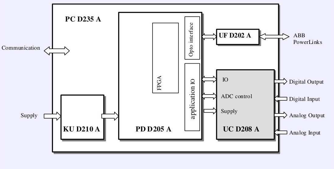
The module is assembled from 4 core sub-boards:
- PD D205 A: FPGA-based main control module
- UC D208 A: Application I/O interface board, receiving all external terminal signals
- KU D210 A: Internal module power supply unit
UF D202 A: Optical fiber communication module, realizing high-speed optical interconnection with the excitation controller
Environmental and Reliability Parameters
| Item | Parameter |
| Operating Temperature | -25℃ ~ +70℃ |
| Relative Humidity | 5%‑95% (at 40℃) |
| Vibration Standard | IEC 60255‑21 |
| EMC | IEC/EN 61000 |
| Hardware Failure Rate | 7082FIT (at 40℃) |
| Redundancy Capability | Supports hardware redundancy with dual PC D235 A for all system interfaces |
System Positioning and Application Scenarios
System Affiliation: Mainly used in UNITROL®6000 (X‑power) static excitation system, acting as the signal interface hub of the excitation regulator. It collects analog signals, digital signals and temperature signals from the generator site, outputs control commands and protection action contacts, and completes signal interaction between the excitation system, plant DCS and field sensors.
Applicable Units: Synchronous generator excitation systems for thermal power, hydropower and gas turbine units.
Spare Part Attribute: Listed as a key spare part of ABB UNITROL6000 and covered under Excitation Care service. Damage to this module will directly cause failure of excitation I/O channels, and in severe cases lead to excitation system trip. Power plants generally stock this critical spare part to reduce the risk of unplanned outages.
PCD235A101 Compatible Excitation System Complete Models
Only applicable to UNITROL®6000 series excitation systems:
- UNITROL 6000 Light
- UNITROL 6000 Medium (formerly UNITROL6080)
- UNITROL 6000 X‑power (formerly UNITROL6800)
- UNITROL 6000 Nuclear (nuclear power version)
Not compatible with legacy UNITROL5000 and UNITROL‑F excitation systems.
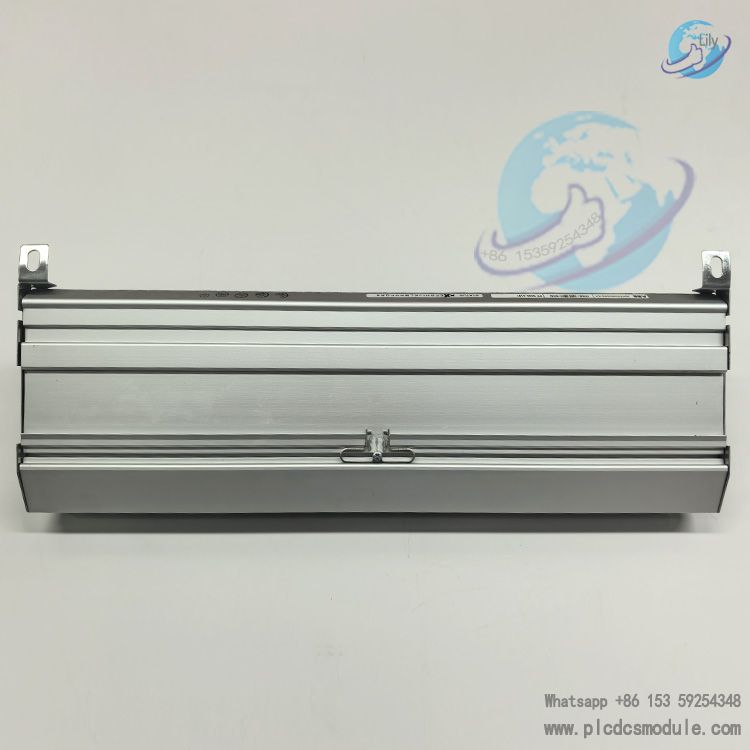
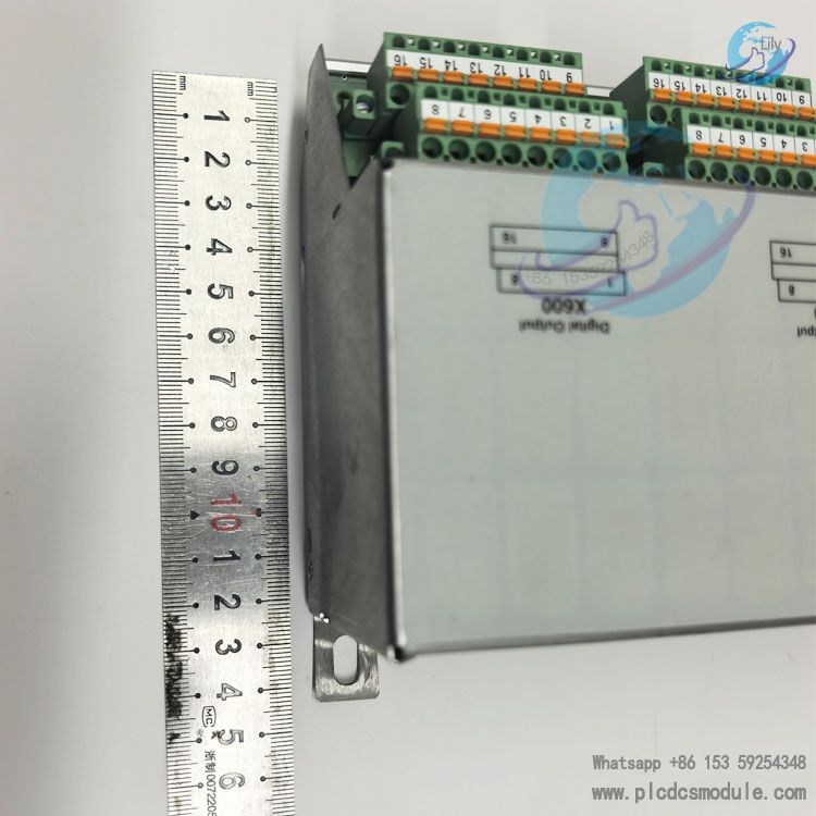
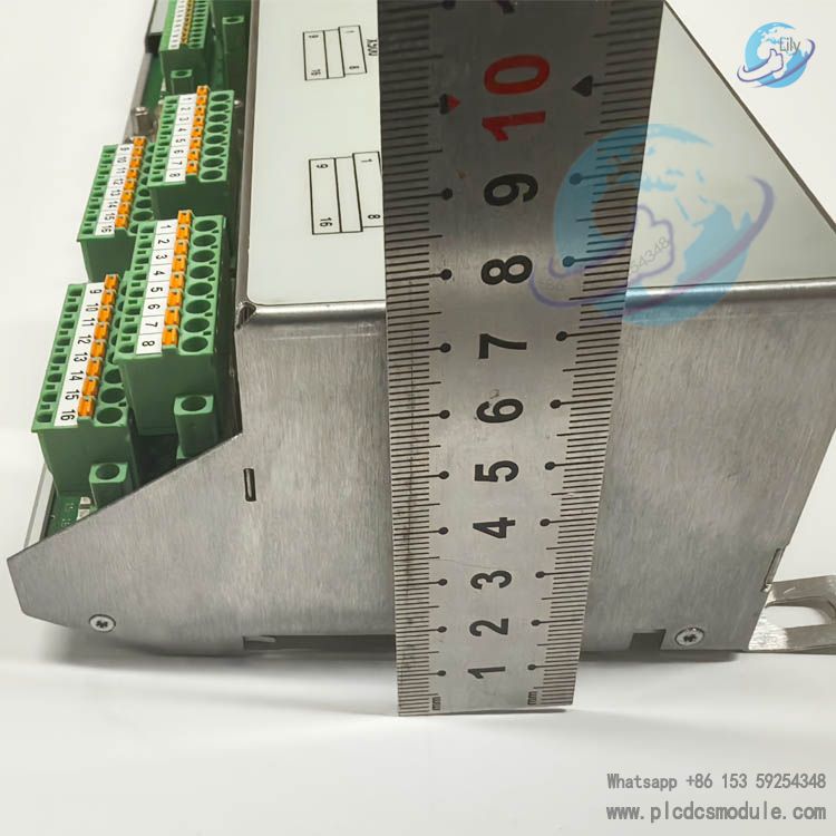
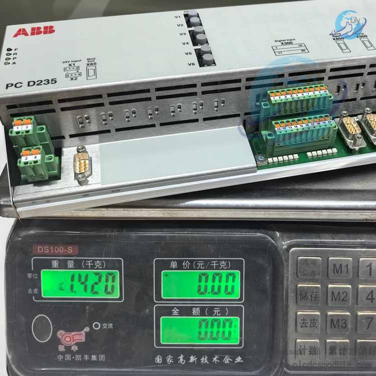
Product dimensions and weight:
Net weight:1.42kg
Dimensions:39*15*8cm
Matching Boards for PCD235A101 (Must be installed in the same rack)
| Board Name | Order Number | Function Description |
| PC D230 (CCM Main Control Board) | 3BHE022291R0101 | UNITROL6000 main control CPU board. PCD235A101 communicates with it via PowerLinks optical fiber |
| UF D202 A | Integrated inside the board | PowerLinks optical transceiver, enabling high-speed optical communication with the main controller |
Comparison within the same series: PC D232 A (3BHE022293R0101, PEC80‑CIO) is the previous generation I/O board. PCD235A101 (PEC80‑CIO‑FU) is its upgraded version adopting FPGA architecture. The two cannot be directly hardware interchanged; matching firmware and project configuration are required.
System Architecture Requirements
- Single-channel system: Configurable with one PCD235A101, no I/O redundancy
- Dual-channel (redundant system): Requires two PCD235A101 boards plus two PC D230 main control boards to achieve full hardware I/O redundancy
- Software Tools: ECT, PECinstaller (special commissioning software for UNITROL6000). Standard ABB PLC software cannot configure this board.
Advantages of PCD235A101
- High integration and complete interfaces. A single board integrates DI, relay DO, AI, AO, PT100/PTC temperature measurement, isolated RS485 and PowerLinks optical fiber. One board handles most external signal interactions of the excitation system and reduces the quantity of boards inside the rack.
- Full support for hardware I/O hot redundancy. Supports dual-channel full interface redundancy. Faulty boards can be unplugged and replaced online. Failure of a single I/O board will not directly cause unit trip, suitable for thermal power, hydropower, nuclear power and other generator sets demanding ultra-high reliability.
- FPGA hardware architecture. Onboard FPGA processing unit delivers fast signal acquisition response. Equipped with independent hardware watchdog and hardware self-diagnosis; faults can be quickly located and reported to the excitation system and DCS.
- Wide-temperature industrial design. Operating temperature -25℃~+70℃ to adapt to high-temperature environments inside power plant excitation cabinets. Complies with IEC vibration and EMC standards for complex electromagnetic environments in power plants.
- Strong temperature measurement capability. Natively supports PT100 and PTC 3-wire temperature measurement, directly collecting temperature of power devices and rotors without additional external temperature acquisition modules.
Disadvantages and Limitations
- Highly specialized with poor versatility. It is not a general-purpose PLC I/O module. Firmware is customized for UNITROL6000 excitation systems. It cannot run independently without the PC D230 main control board and cannot be directly deployed in other non-excitation AC800PEC projects, leading to high reuse costs.
- Cannot directly replace legacy PC D232A. Although rack form factor is compatible, FPGA and firmware logic differ. Direct replacement will trigger I/O anomalies. Replacement requires project modification and matching firmware download by professional engineers.
- High cost for redundancy configuration. Full I/O redundancy requires 2 sets of main control boards plus 2 sets of I/O boards, bringing high hardware and commissioning costs. Redundancy cannot be realized with a single board.
- Limitations brought by parallel connection of external signals. In redundant mode, analog inputs require transmitters to output signals in parallel to two boards. Some transmitters have insufficient drive capacity and may result in analog reading deviation, requiring proper transmitter selection.
- Limited use of RS485 interface. The onboard isolated RS485 hardware interface is dedicated for Bender insulation monitoring relays, and cannot be used as a general debugging port or DCS communication port. External communication relies on the main control board; this board has no direct external Ethernet communication.
- High procurement cost for spare parts. It is an imported dedicated excitation spare part. Power plants are recommended to stock spare parts in advance.
- Redundancy only resolves board faults and cannot compensate for external sensor failures. Even with dual I/O boards configured, signal faults will still be triggered if external transmitters or sensors are disconnected.
Redundancy Configuration Description for PCD235A101 (PC D235 A101)
Important Precondition: PCD235A101 is a CIO‑FU integrated I/O board. It is merely an I/O interface. Complete I/O redundancy must be built upon the UNITROL6000 dual redundant master channel architecture (dual PC D230 master control boards). Single-channel master control cannot achieve true hardware redundancy of this board. Two PCD235A101 boards can implement hardware hot redundancy of all I/O interfaces to realize dual backup for acquisition, output and communication links. Failure of one single board will not trigger unit trip, and the faulty board supports online maintenance and replacement.
1. Hardware Prerequisites
- System Architecture: UNITROL6000 must adopt dual-channel (A/B channel) configuration with fully configured Channel A master PC D230 and Channel B master PC D230. CIO-FU redundancy cannot be enabled in a single-channel system.
- Board Quantity: Deploy two identical PCD235A101 (3BHE032025R0101) boards. Firmware and hardware versions must be consistent. Mixing PC D232 A (CIO) and PCD235A101 is prohibited.
- Redundant Power Supply (Power supply for each individual board): Each PCD235A101 requires independent dual 20‑28VDC redundant power supply with max. 2A. The I/O board of Channel A is powered by Channel A 24V power supply, while Channel B I/O board uses Channel B 24V power supply. It is forbidden for the two boards to share the same 24V power source.
- PowerLinks Fiber Optic Link
Channel A PCD235A101 fiber connects to the optical port of Channel A master PC D230;
Channel B PCD235A101 fiber connects to the optical port of Channel B master PC D230;
Use ABB original UF D202A optical modules and dedicated PowerLinks fiber cables. Fiber links must be kept intact. Optical fiber serves as the only high-speed channel for real-time data exchange between master controller and I/O board. - Board Address Setting: Set different DIP switch device addresses for the two boards (within the range of 0‑15). Address conflict between Channel A and Channel B I/O boards is not allowed.
2. Wiring Principles for External Signals (Redundant I/O Signals)
Under UNITROL6000 dual-channel mode, signals are divided into acquisition input signals and output contact signals with different wiring methods.
- Analog Input, Digital Input, PT100/PTC Temperature Input: Field sensor signals are wired in parallel to the corresponding identical terminals of both A and B PCD235A101 boards. Both A/B channels collect the same external signal simultaneously. System software performs dual-channel signal comparison and quality judgment. If the acquisition of one I/O board fails, the other channel takes over the signal.
Note: Pay attention to the driving capability of the signal source for parallel analog signals. Confirm that 4‑20mA transmitters can drive two parallel loads. - Relay Output Contacts (alarm, trip, interlock contacts): Relay outputs shall not have paralleled terminals. Channel switching is realized via internal dual-channel logic of the excitation system.
Critical trip and protection outputs: Contacts of Channel A and B are connected in series; trip output is generated only when both channels act simultaneously.
Normal status and alarm outputs: The software selects the active main channel for output while the standby channel remains on standby. Output will automatically switch to standby channel upon main channel failure. - RS485 (Bender insulation monitoring) Interface: The RS485 bus of Bender relay is connected to the isolated RS485 interfaces of both A and B PCD235A101 boards. Dual channels read insulation monitoring data concurrently.
Common Risks & Precautions
- Misconception: If only two boards are installed without enabling dual-channel mode in software, hardware will not automatically implement redundancy. They are merely two independent I/O boards without switching logic.
- Inconsistent firmware and project versions between two boards will cause dual-channel desynchronization and signal fluctuation. The A/B channel projects must be fully identical.
- When external input signals are connected in parallel, insufficient transmitter driving capability will result in inaccurate analog readings. Replace with transmitters of stronger driving capacity if required.
- Hot-plugging of RS485-Bender bus is not recommended. Disconnect bus wiring before plugging/unplugging to prevent bus interference.
- Redundant I/O cannot fix faults of external sensors themselves. If external sensors are disconnected, signal faults will still be reported even with dual I/O boards. Redundancy solves hardware faults of the board card rather than external sensor faults.
- The redundancy function of this board is a system-level feature of UNITROL6000. Standalone hardware redundancy separated from UNITROL excitation system is not supported.
3. Fault Phenomena (Redundancy Abnormality)
- Large deviation of dual-channel I/O values, alarm "I/O channel signal mismatch";
- One board reports hardware fault while the other cannot automatically become the master;
- Unit trips directly after board removal, indicating redundancy configuration is not actually effective. Recheck hardware, fiber optics and software parameters.
Tip: Redundancy modification counts as a major change to the excitation system. Complete redundancy configuration modification is not recommended online while the unit is in operation. Prefer to perform the work during shutdown maintenance.
FAQ
Q1: What is the order number of PC D235 A101? What are its aliases?
A: Order No.: 3BHE032025R0101; Aliases: PCD235A101, CIO‑FU, PEC80‑CIO FU. It is a dedicated comprehensive I/O board for UNITROL®6000 excitation system.
Q2: Is PC D235 A101 a CPU master board and can it work standalone?
A: It is NOT a CPU master board but an I/O interface board. It cannot run independently. It must cooperate with UNITROL6000 master boards (such as PC D230) and run on AC800PEC platform firmware. Its firmware logic is customized for excitation scenarios and cannot be directly used as a general PLC I/O module.
Q3: Does PC D235 A101 support redundancy? How is it implemented?
A: It supports hardware hot redundancy of all interfaces. Deploy two PC D235 A101 boards in the system to achieve redundancy for all I/O and communication interfaces. Failure of a single board will not directly cause unit trip, improving reliability of the excitation system.
Q4: What is the purpose of the RS485 interface on the board?
A: The isolated RS485 port is specially for Bender insulation monitoring relays. It is NOT a general configuration or commissioning port. High-speed data interaction with the master board relies on ABB PowerLinks fiber links.
Q5: What sensors can the temperature interface connect to?
A: 3 channels of 3-wire temperature measurement interface supporting PT100 platinum RTD and PTC thermistor. PT100 measuring range: -40℃~+240℃; PTC operates at 500Ω resistance.
Q6: What equipment and industries is it mainly used for?
A: Exclusively for UNITROL®6000 excitation control systems. Applications include thermal power, hydropower (pumped storage), nuclear steam turbine generators, nuclear island emergency diesel generators; also for excitation of high-power synchronous drive motors in steel, chemical and oil & gas industries. The hardware can theoretically be applied to other AC800PEC power electronic devices, but program redevelopment is required, which is rarely adopted on site.
Q7: Can it directly replace PC D232 A (PEC80‑CIO)?
A: Direct interchange is not allowed. There are differences in hardware and FPGA firmware between the two. System configuration, program version and terminal wiring need to be checked. Replacement must be evaluated by ABB professional engineers.
Q8: What are the power supply requirements for the module?
A: Redundant 24VDC power supply, voltage range 20‑28VDC, max. current 2A. Two independent 24V power supplies must be used for redundancy.
Q9: What is the operating temperature range? Can it run long-term inside high-temperature cabinets?
A: Operating temperature: -25℃ ~ +70℃. Cabinet operating temperature must not exceed the upper limit of 70℃, with relative humidity 5%‑95% @40℃. Cabinet heat dissipation must be satisfied. It complies with IEC 60255‑21 vibration and IEC/EN 61000 EMC standards.
Tag document:
ABB PCD235A101, 3BHE032025R0101, PC D235 A101, CIO‑FU, Integrated Input/Output Module, I/O Board, FPGA Board, UNITROL6000, AC800PEC, Excitation System, Dual-channel Redundancy, Hardware Hot Redundancy, PT100, PTC, PowerLinks, Generator Excitation, Thermal Power, Hydropower, Nuclear Power, Excitation Spare Parts, Excitation‑Care, Special I/O Board, Cannot Run Independently