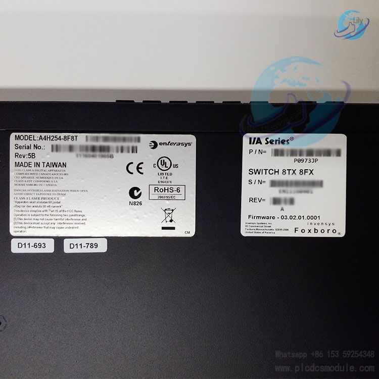
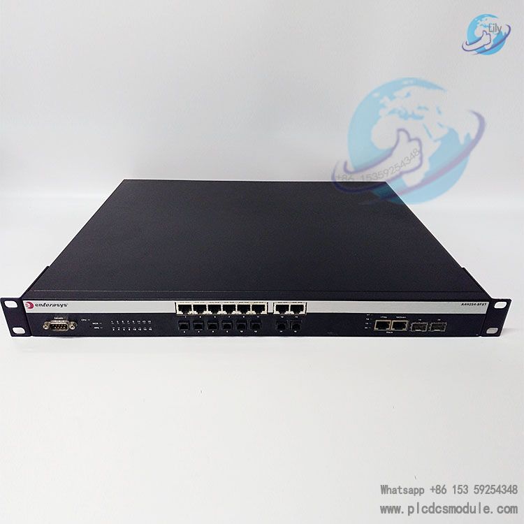
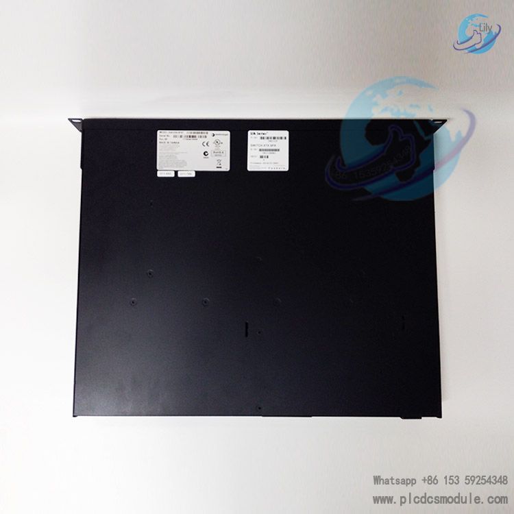
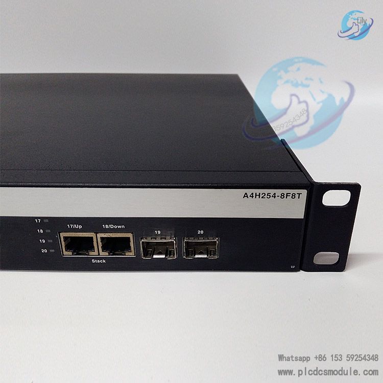
Note; All products on this site are special products, the market price has been fluctuating, the specific customer service offer shall prevail, because the product is a new product, the picture is not a real shot, please confirm with customer service before placing an order model and product, price and other details, the site used, new are for sale, please contact customer service communication. The Enterasys A4H254-8F8T is a stackable Fast Ethernet switch belonging to the A4 series, which has the ability to flexibly expand and adapt to changes in network requirements. It provides a management platform and backbone uplink for a stacked group of up to 8 A4 switches, and also supports redundant power supplies to reduce downtime caused by internal power supply failures or AC power issues.
DATA SHEET
 Enterasys A4H254-8F8T.pdf
A4H254-8F8T.pdf
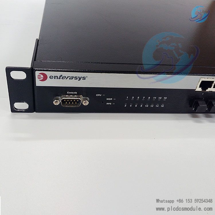
Port Configuration
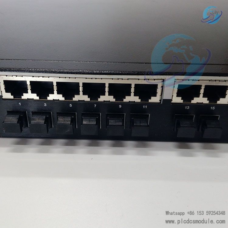
8 10/100Base-T ports (marked with odd numbers 1 - 15)
8 100Base-FX MT-RJ ports (marked with even numbers 2 - 16)
2 10/100/1000Base-T RJ45 ports, which can be used as stacking ports or Ethernet uplink ports (marked 17 and 18)
2 Gigabit Ethernet SFP ports (marked 19 and 20); each SFP port supports the installation of 1000BASE-SX, 1000BASE-LX, or 1000BASE-T SFP pluggable transceivers
Processor and Memory
Processor: MPC8241, 266 MHz
Synchronous Dynamic Random Access Memory (SDRAM): 256 MB
FLASH Memory: 32 MB
Physical Specifications
Dimensions: 44 W x 4.4 H x 36.5 D cm (17.3 W x 1.7 H x 14.4 D in)
Approximate Weight: 4.78 kg (10.5 lb)
Power Specifications
Power Consumption: 47.1 W
Input Frequency: 50 to 60 Hz
Input Current: Maximum 1.0A
Thermal Output: Same as power consumption
Environmental Specifications
Operating Temperature: 0°C to 50°C (32°F to 122°F)
Storage Temperature: -40°C to +70°C (-40°F to 158°F)
Operating Relative Humidity: 5% to 95% (non-condensing)
Altitude: Up to 10,000 feet during operation; tested up to 15,000 feet when not in operation
Performance
Throughput Capacity at Wire Speed (switch/stack): 8.3 Mpps / 66.7 Mpps
Switching Capacity (switch/stack): 11.2 Gbps / 89.6 Gbps
Stacking Capacity (switch/stack): These switches do not have dedicated stacking ports; 10/100/1000 ports can be used for stacking or uplinks
Total Throughput Capacity (switch/stack): 11.2 Gbps / 89.6 Gbps
Features
Stack Connections
The switches have front panel RJ45 ports for connections in a stack configuration. The stacking cables used for the connections must be standard Category 5 or better UTP cable. The stack can be connected in a closed loop or daisy chain manner. The closed loop configuration has the advantage of redundancy, eliminating any single point of failure. Up to 8 switches can be stacked together through standard Category 5 or better UTP cables, and the stacking cables allow the entire stack to operate with a single IP address.
Redundant Power Supply Capability
The A4 has power supply redundancy capability when connected to an optional external redundant power supply, such as STK-RPS-150PS (a 150-watt DC power supply that provides redundant power for A4 switches). If the internal power supply fails, the RPS automatically assumes the role of the internal power supply without interrupting network traffic. The internal power supply and RPS each have their own AC power connection, which enables the connection of each power supply to a different AC power circuit for additional AC power source redundancy.
Management
Management of the switch can be either in-band or out-of-band. In-band remote management can be implemented using Telnet, Enterasys Networks' NetSight® management application, or the WebView application. Out-of-band management is provided through the DB9 Console port connector on the front panel, which can use a VT100 terminal or a VT100 terminal emulator.
Switch Configuration Using WebView
Enterasys Networks' HTTP-based Web management application (WebView) is an intuitive web tool for simple management tasks.
Switch Configuration Using CLI Commands
The CLI commands enable you to perform more complete stackable switch configuration management tasks. For CLI command set information and how to configure the module, refer to the Enterasys A4 CLI Reference.
Standards Compatibility
The 100BASE-T ports are compliant with the following standards and operations:
Installation Related
- Installing the Switch on a Flat Surface
When installing the switch on a flat surface, the installation of the rubber feet is recommended to prevent the switch from sliding on a flat surface. Place the switch on a sturdy flat surface, install the rubber feet on its four corners, and then return the switch to its upright position. - Rack Mounting the Switch
To install the switch in a 19-inch rack, you need two rackmount brackets and mounting screws shipped with the switch, and four customer-supplied screws to attach the switch to a standard 19-inch rack. Fasten the rackmount brackets to the switch with screws, then position the switch between the vertical frame members of the 19-inch rack and fasten it securely to the frame with screws. Considerations Prior to Installation
Before starting the installation procedure, notify the network administrator.
Follow the installation procedures in the order as presented in this guide.
Do not connect the switch to the network until you have established the correct IP address.
Required Tools
A Phillips screwdriver is required to install the switch into a rack.
Installation Methods
Safety Information
- Electrical Hazard
Only qualified personnel should perform installation procedures. - Laser Safety
The single mode interface modules use Class 1 laser transceivers. When using a fiber optic media expansion module, never look at the transmit laser while it is powered on. Also, never look directly at the fiber TX port and fiber cable ends when they are powered on. Do not use optical instruments to view the laser output, as this increases eye hazard. When viewing the output optical port, power must be removed from the network adapter.
Regulatory Compliance
This product complies with a number of regulatory standards, including relevant standards such as FCC, Industry Canada, Class A ITE, VCCI, BSMI EMC, as well as European directives on Restriction of Hazardous Substances (RoHS) and Waste Electrical and Electronic Equipment (WEEE).
TroubleshootingProblems can be diagnosed by checking the status of LEDs. Different colors and states of different LEDs (such as MGR, RPS, UP, DOWN, CPU, Link/Activity, etc.) represent different device states. A troubleshooting checklist is also provided, covering common problems such as all LEDs being off, no local management startup screen, inability to contact the switch through in-band management, along with possible causes and recommended solutions. If you forget the A4 login password, you can use the password reset button to reset the password to the default value.


 3005319639