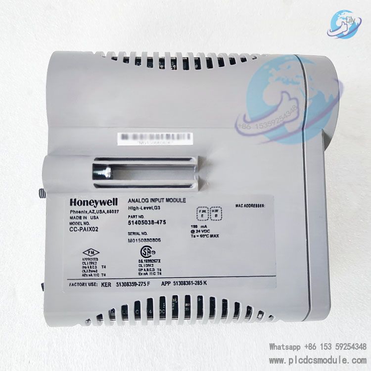
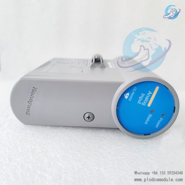
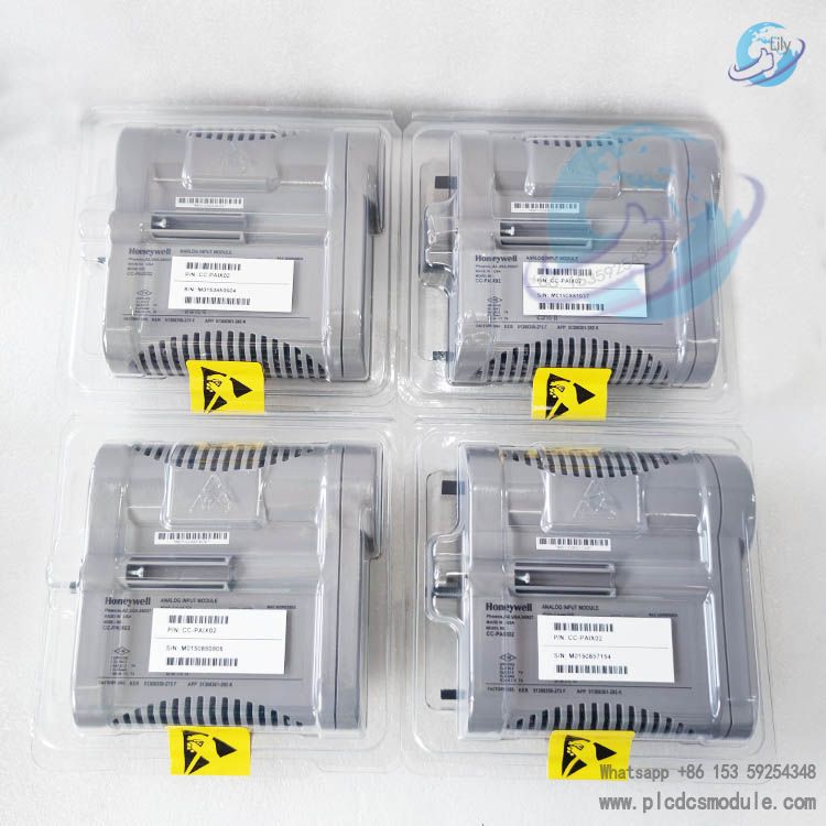
The core positioning of this module is as follows:
Compatibility: It enables seamless integration with the Honeywell Experion PKS control system, supports version R410 and above, and can work in coordination with Series C components such as the C300 Controller and Control Firewall;
Signal Types: It is compatible with two-wire / self-powered transmitters, and supports 4-20 mA (milliampere) current signals as well as 0-5 V (volt), 1-5 V (volt), and 0.4-2 V (volt) voltage signals;
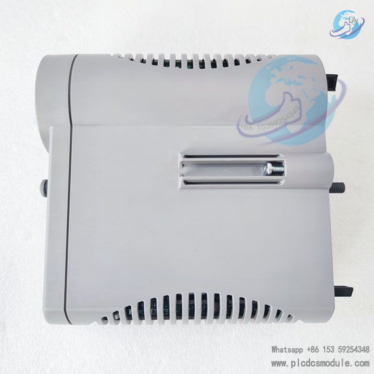
Environmental Adaptability: It adopts a wide-temperature design, with an operating temperature range of -40°C to +70°C; it is compatible with hazardous areas of Class 1, Div 2 / Zone 2 (when used with GI/IS IOTA components), making it suitable for harsh industrial environments such as chemical industry and energy industry;
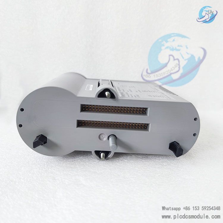
Redundancy Capability: It supports redundant configuration of I/O Modules (IOM) (when used with CC-TAID11 redundant IOTA components). The switchover time between the main module and the standby module is no more than 500 ms (millisecond), which can ensure that critical industrial processes are not interrupted.
DATA SHEET
Performance Parameters
Application Fields
Petrochemical Industry
Application Scenarios: Acquisition of temperature, pressure, and liquid level signals from reactors; pipeline flow monitoring (e.g., paired with turbine flowmeters and differential pressure transmitters).
Value: Supports indirect access to hazardous areas (Class 1, Div 2/Zone 2) (requires matching with GI/IS IOTA), ensuring safe monitoring of chemical processes.
Energy and Power Industry
Application Scenarios: Acquisition of boiler steam pressure/temperature in thermal power plants; monitoring of voltage/current signals in substations; current monitoring of combiner boxes in new energy (photovoltaic/wind power) systems.
Value: The wide-temperature design is suitable for outdoor/high-temperature equipment room environments; redundant configuration prevents data acquisition interruptions, ensuring the stable operation of power systems.
Smart Manufacturing and Automotive Industry
Application Scenarios: Temperature and humidity monitoring in painting workshops of automobile production lines; acquisition of signals from machine tool processing accuracy sensors (e.g., 0-5V signals from displacement sensors).
Value: The fast scanning rate (50ms) meets real-time control requirements, and the anti-interference capability is suitable for complex electromagnetic environments in factories.
Municipal and Environmental Protection Industry
Application Scenarios: Water quality sensor monitoring in sewage treatment plants (e.g., 4-20mA signals from dissolved oxygen and pH transmitters); temperature monitoring of urban heating pipe networks.
Value: The high input impedance reduces signal attenuation, making it suitable for long-distance wiring (supports calculation of maximum on-site wiring resistance, with the formula: , where Vtx is the voltage requirement of the transmitter).
Working Principle
Signal Acquisition Phase
Signal Conditioning Phase
Filtering: High-frequency noise (such as 60Hz power frequency interference) is removed through an RC filter circuit.
Current/Voltage Limiting: A built-in 250Ω resistor limits current input, and ±30V overvoltage protection prevents module damage.
Isolation: Galvanic isolation between channels (optional, requires matching with GI/IS IOTA) prevents ground loop interference.
A/D Conversion Phase
Data Transmission Phase
Self-Diagnosis Phase
Power supply voltage (24V DC ±10%);
A/D conversion accuracy (compared with internal reference values);
Channel wiring (open/short circuit detection);
Abnormal states are fed back to the Control Builder via the I/O Link, triggering software fault alarms (e.g., "VREFFAIL" for reference voltage fault).
Frequently Asked Questions (FAQ)
A: "INPTFAIL" is an input fault. The troubleshooting steps are divided into 3 parts:
Check wiring and power supply: Use a multimeter to measure the transmitter power supply (24V DC is required for two-wire systems to be normal). Confirm that there is no loose or short-circuited wiring (the resistance between terminals should be ≥1kΩ; if open-circuited, re-tighten the wiring).
Verify the signal range: Measure the input signal value (the current should be within 4-20mA, and the voltage within 0-5V/1-5V). If the signal is out of range (e.g., <3.8mA or >20.5mA), check if the transmitter is faulty.
Check the IOTA jumper: For voltage input, confirm that the jumper (e.g., JP1) of the corresponding channel has been disconnected (failure to disconnect will cause a signal short circuit). For differential mode, confirm that the TB2 jumper configuration is correct (refer to the CC-TAID11 terminal table).
A: Yes, but 3 core conditions must be met:
IOTA selection: Use the CC-GAIX21 GI/IS IOTA for non-redundant scenarios and the CC-GAIX11 GI/IS IOTA for redundant scenarios.
Isolator configuration: Intrinsically safe isolators (e.g., MTL4541 for 4-20mA signals) must be connected in series. Ensure the isolators comply with ATEX/CSA certifications (Class 1, Div 2).
Wiring requirements: Use armored shielded cables (e.g., Belden 9463). Avoid parallel routing with power cables, and ground the shield layer at one end (near the module side).
A: Hardware jumpers and software configuration are required. The steps are as follows:
Hardware jumpers (IOTA side): Take the CC-TAID01 non-redundant IOTA as an example. Short the J249-J250 jumpers (marked "DIFF") and disconnect the J248-J250 jumpers (single-ended mode). All 16 channels need to be configured independently.
Software configuration (Control Builder):
a. Open the "Configuration" tab of the IOM block and set "Input Type" to "Differential".
b. Select "Channel Mapping" and confirm that all 16 channels are associated with differential terminals (TB1 + TB2).
c. Verification: Connect a differential signal (e.g., for Channel 1, connect "+" to TB1-1 and "-" to TB2-1). Observe that the PV value has no fluctuation (a fluctuation of ≤±0.05% FS is normal).
Q: If a "VREFFAIL" (reference voltage fault) occurs during module operation, how to handle it?
A: "VREFFAIL" indicates an abnormality in the internal reference voltage. The handling priority is as follows:
Temporary recovery: Power off the module for 10 seconds and then power it on again. If the fault disappears, it is a temporary interference (e.g., power grid fluctuation), and the fault occurrence time and working conditions should be recorded.
Check power supply stability:Use a multimeter to measure the voltage of the IOTA power terminal (TB3), which should be within 24V DC ±10% (21.6V-26.4V). If the voltage fluctuation exceeds 5%, troubleshoot the cabinet power module.
Module calibration: If the power supply is normal, perform "Reference Voltage Calibration" in Control Builder (path: IOM Block → Calibration → VREF Cal) and calibrate using a standard voltage source (e.g., 2.5V reference).
Hardware replacement: If calibration fails, the internal reference voltage chip of the module may be faulty. The CC-PAIX02 module needs to be replaced (note to back up the configuration file).
Q:If the communication between the CC-PAIX02 and the C300 controller is interrupted, how to troubleshoot?
A: Communication interruptions are mostly related to the I/O Link or configuration. The troubleshooting steps are:
Check physical connections:Confirm that the I/O Link cables (gray/purple) between the IOTA and the C300 controller are not loose and the connectors are not oxidized. For redundant configurations, check the active and standby Link cables.
Check Link status:In Control Builder, check the status of the "IOLINK" block. If "Link Status" is "Down", check the I/O Link address jumper (the module address must be consistent with the IOMNUM parameter).
Diagnose module firmware: Use the CTools tool to check the module firmware version, which must be compatible with the C300 controller firmware (the R430 system requires a firmware version ≥V2.0). If incompatible, upgrade the firmware.
Redundancy switch test:For redundant configurations, manually switch between the active and standby modules. If the standby module communicates normally, the I/O Link interface of the active module is faulty, and the active module needs to be replaced.
Customers who purchased this product are also browsing the following products:
Honeywell CC-PAIN01 51410069-175 High-Level Analog Input Module
ABB PNI800A Plant Network Interface Module
HIMA F8652X 984865265 Central module
Honeywell LCNP4E 51405098-100 Interface Card




 3005319639