The HONEYWELL 261A1812P010 is an industrial solar-blind ultraviolet flame sensor belonging to the 261A series, matched with LG1093 coding. It is specially designed for real-time flame monitoring of industrial combustion systems.It identifies flames generated by hydrocarbon fuel combustion via the ultraviolet spectrum ranging from 190 nm to 270 nm, and can filter out interference sources including sunlight, artificial lighting, and blackbody radiation from high-temperature equipment.
This sensor outputs standard microampere-level flame signals suitable for long-distance signal transmission. It is widely compatible with flame amplifiers and combustion program controllers to implement flame-out interlock protection. It adapts to harsh working conditions of various industrial combustion equipment such as gas turbines, industrial boilers and heating furnaces.
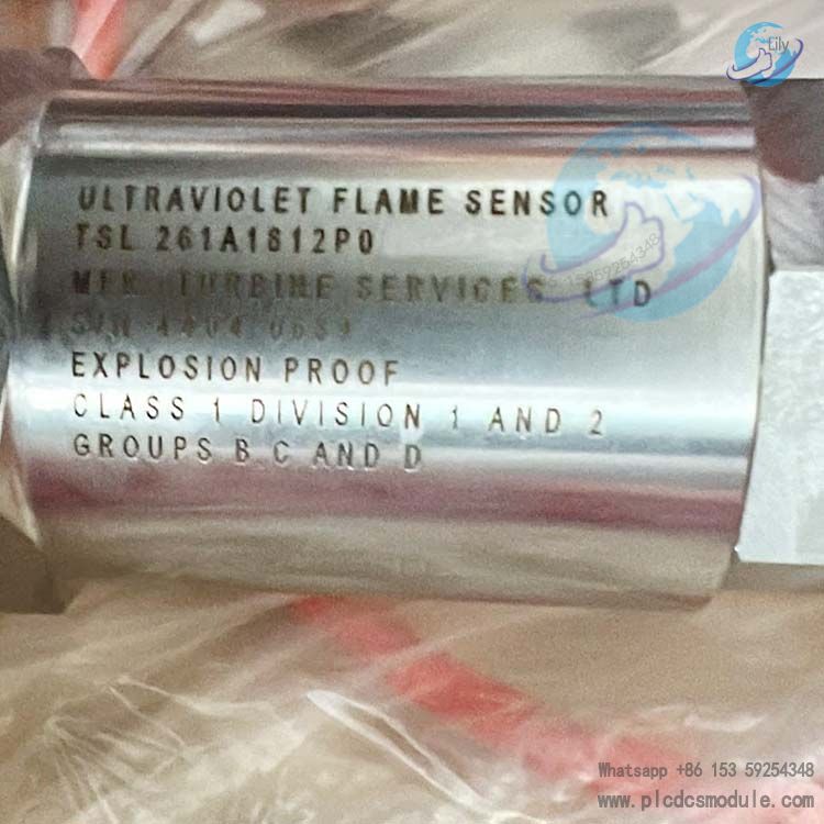
Model Breakdown
Full Model Number: 261A1812P010Associated Material Code: LG1093AA24
Segment-by-Segment Definition
- 261A: Product series code, denoting the industrial long-cable ultraviolet flame sensor product line.
- 1812: Structure and cable specification code, defining probe thread size, base cable length, and alloy housing material.
- P: Operating condition adaptation marker. P stands for standard general industrial type, without high-temperature reinforcement or special explosion-proof thickened housing.
- 010: Sub-version code that differentiates signal output parameters and compatible amplifier models. 010 is the base universal version; upgraded replacement models include 261A1812P012 and 261A1812P013.
Product Features
Electrical Specifications
- Power supply: Matches supporting amplifiers rated at 28 VDC; maximum operating current: 15 mA.
- Analog current signal output: Flame-absent signal <1 μA; flame-present signal 5~25 μA.
- Terminal wiring compatible with cables of 0.5~1.5 mm² cross-sectional area; fitted with M20 cable gland for cables with outer diameters ranging from 7 mm to 13 mm.
Mechanical Specifications
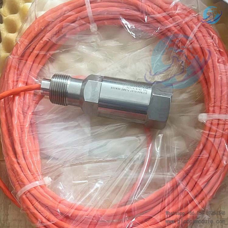
- Standard threaded mounting design, compatible with standard sight tubes of combustion equipment.
- Integrated high-temperature resistant alloy probe housing; total unit weight approx. 300 g, offering excellent suitability for compact installation spaces.
- Industrial oil-resistant orange dedicated signal cable, featuring anti-aging and flex-resistant properties.
Environmental & Service Life Specifications
- Storage temperature range: -20 ℃ to +60 ℃; operating humidity: 5%–95% non-condensing.
- Built-in UV sensing lamp rated for a base service life of 10,000 hours; overall unit design service life: 10 years.
- Tolerates cooling purge air pressure up to 1.5 bar; purge air can be used to clean the sight window.
Safety & Compliance Specifications
- Safety class: Class 1; pollution degree: internal Grade 2, external Grade 4.
Certified to EN298 combustion safety standard and SIL3 functional safety certification, complying with mandatory safety regulations for industrial combustion systems.
Application Fields
Power Industry
- Flame monitoring for gas turbines, waste heat boilers, power station burners, and natural gas booster units.
Petrochemical Industry
- Tube furnaces, cracking furnaces, oil & gas flares, and combustion assemblies matched to chemical reaction kettles.
Metallurgy & Glass Industry
- High-temperature combustion conditions of metallurgical heat treatment furnaces, glass melting furnaces and annealing furnaces.
HVAC & Industrial Boilers
- Gas-fired hot water boilers, steam boilers, direct-fired absorption chillers and hot blast stoves.
Waste Incineration Industry
- Auxiliary burners of incinerators and tail gas heating combustion systems.
Fine Chemical & Pharmaceutical Industry
- Small process heating furnaces and explosion-proof laboratory combustion equipment.
Working Principle
- The core detection component of the 261A1812P010 is a dedicated solar-blind UV phototube. Hydrocarbon fuel combustion emits short-wave ultraviolet light in the 190–270 nm band. This UV spectrum does not appear in sunlight, indoor lighting or high-temperature metal surfaces, featuring exclusive flame identification characteristics.
- After the sensor’s phototube receives the short-wave UV light from flames, photoelectrons are generated internally and converted into continuous analog current signals transmitted to the matched flame amplifier. The amplifier distinguishes two operating conditions based on current values: a reading of 5~25 μA confirms normal flame presence, while a reading below 1 μA indicates flame extinction.
- The amplifier transmits signals to the combustion program controller, which executes safety logic according to input signals:
- If the flame is normal, continuous fuel supply is maintained.
- If the flame extinguishes unexpectedly, the controller immediately cuts off the fuel valve and triggers audible & visual alarms simultaneously, preventing safety hazards such as explosions and flashbacks caused by accumulation of unburned fuel.
Frequently Asked Questions
Q1: How to choose between model 261A1812P010 and 261A1812P012?
- A1: 010 is the original base universal version, while 012 is its upgraded replacement model with fully compatible parameters. Prioritize 012 for new projects. If the original 010 sensor on existing equipment malfunctions, it can be directly replaced with 012 without modifying wiring or mounting structures.
Q2: Can this sensor work alone without a matched amplifier?
- A2: It cannot operate independently. The sensor only outputs weak microampere-level current signals that cannot be directly recognized by combustion controllers. It must be paired with the dedicated EG1033 series flame amplifier for signal conversion and amplification.
Q3: Which industrial working conditions are unsuitable for 261A1812P010?
- A3:
- High-risk refining processes requiring continuous automatic self-test functions and ultra-high explosion-proof ratings: select C7061F instead.
- Small commercial boilers and short-distance wiring scenarios: prioritize the compact C7035A model.
- Ultra-high-temperature kilns with long-term operating temperatures exceeding 85℃: adopt the high-temperature reinforced variant LG1093AD02.
Q4: Is the mounting sight tube required to be purchased together with the sensor?
- A4: Sight tubes are not standard accessories of the sensor and must be ordered separately. Carbon steel sight tubes are recommended; stainless steel and galvanized pipes are prohibited, as such materials reflect ultraviolet rays and reduce detection sensitivity.
Q5: What troubleshooting directions should be followed if frequent false flame-out alarms occur during equipment operation?
- A5: Prioritize four inspection items:
- Carbon deposits and oil stains covering the sensor quartz window, blocking ultraviolet light transmission.
- Damaged cables with failed shielding, causing signal interference from inverters and motors.
- Excessively long sight tubes or offset mounting angles, which fail to fully capture the flame root.
- Unstable supply voltage of the matched amplifier leading to disordered output signals.
Q6: What is the service life of the sensor’s UV sensing tube, and can the tube be replaced individually?
- A6: The continuous operating lifespan of the sensing tube is 10,000 hours. This sensor adopts an integrated sealed structure, and the sensing tube cannot be disassembled or replaced separately. When signal attenuation or tube failure occurs, the entire sensor unit must be replaced.
Q7: How to resolve unstable sensor signals under low-temperature winter conditions?
- A7:
- Inspect the sealing of cable terminals to prevent condensed moisture from entering wiring terminals.
- Install a simple thermal insulation shield outside the sensor to avoid direct exposure of the probe to sub-zero cold airflow.
- Calibrate the supply voltage of the amplifier, as voltage fluctuations under low temperatures will amplify signal errors.
Q8: What operational taboos should be observed during daily inspection and window cleaning?
- A8:
- Do not wipe the quartz window with strong organic solvents such as acetone or banana oil, which will corrode the light-transmitting coating.
- Do not polish the window with rough rags or steel wool pads, as scratches will reduce ultraviolet transmittance.
- Do not disassemble the sensor live without shutting down the equipment: high-temperature hot gas from the furnace may cause scalds, and hot plugging will burn the signal terminals of the amplifier.
Recommended Models of the Same Brand
261A1812P010 Long-Cable UV Flame Sensor261A1812P012 Upgraded Long-Cable UV Flame Sensor261A1812P013 Explosion-Proof Reinforced Long-Cable UV Flame SensorLG1093AA44 UV Flame Sensor for Gas Turbine Special UseLG1093AC01 ATEX-Certified Explosion-Proof UV Flame SensorLG1093AD02 High-Temperature Resistant UV Flame SensorLG1093AE03 UV Flame Sensor for Ultra-Long Distance Signal TransmissionC7035A1023 MiniPeeper Compact UV Flame SensorC7061A1020 Standard UV Flame Sensor with Dynamic Self-Check FunctionC7061F1003 Explosion-Proof UV Flame Sensor with Dynamic Self-Check FunctionC7012E1112 PurplePeeper UV Flame SensorEG1033 Flame Signal Amplifier ModuleRM7897A2002 Integrated Combustion Program Controller