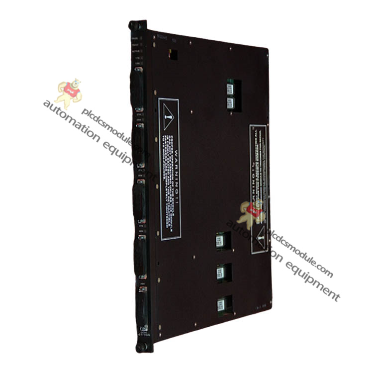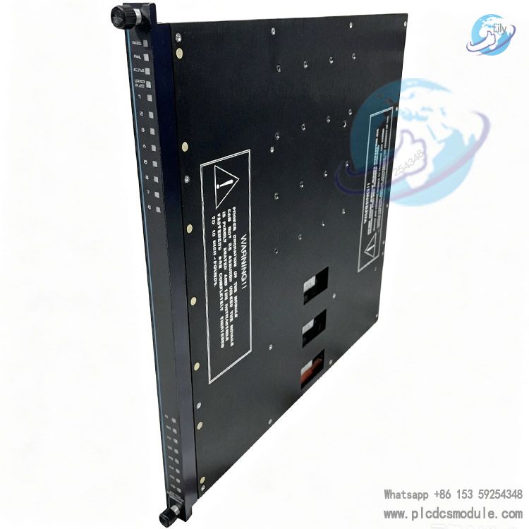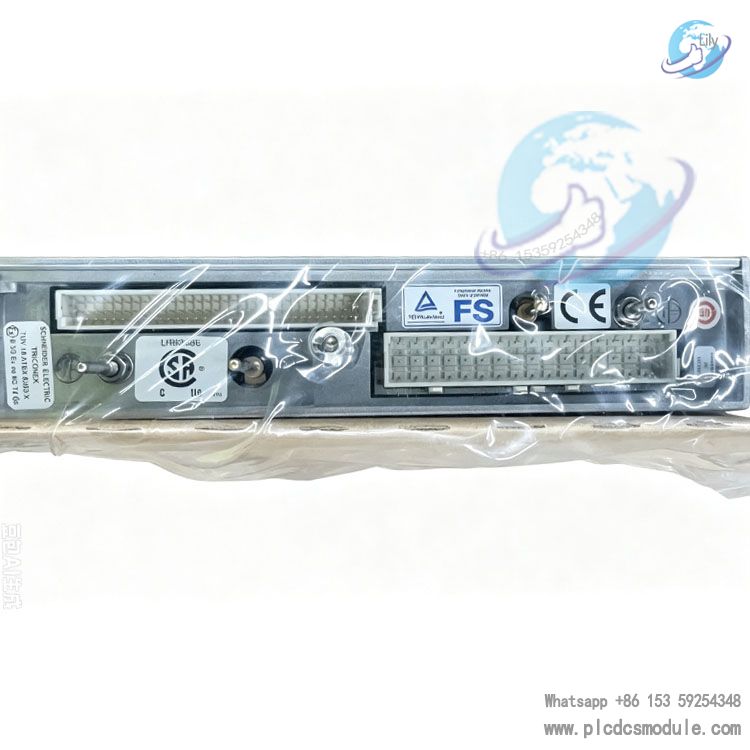
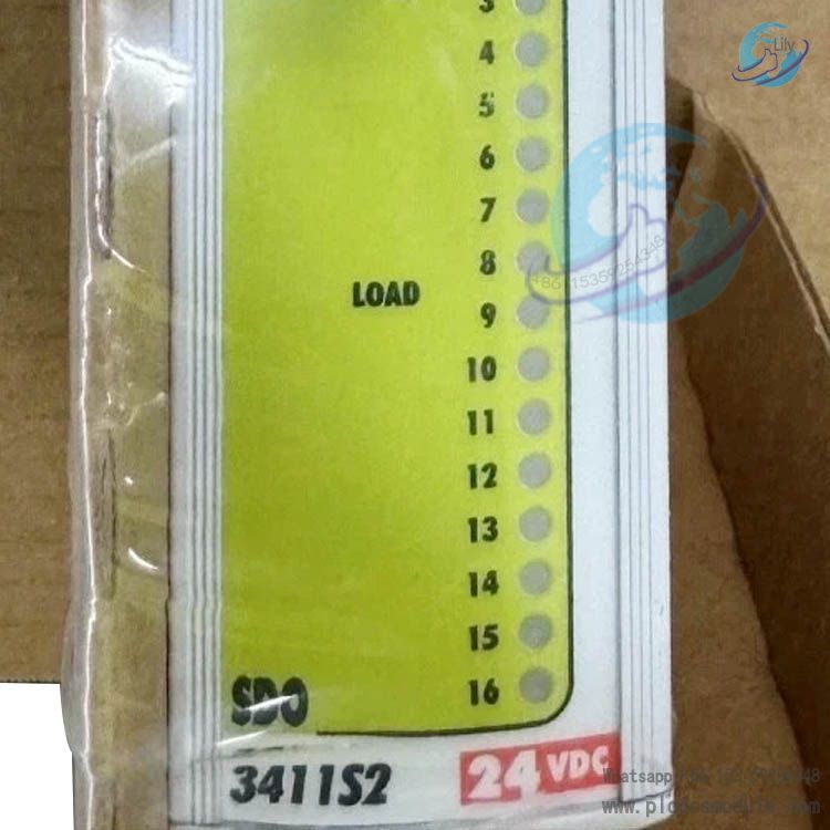
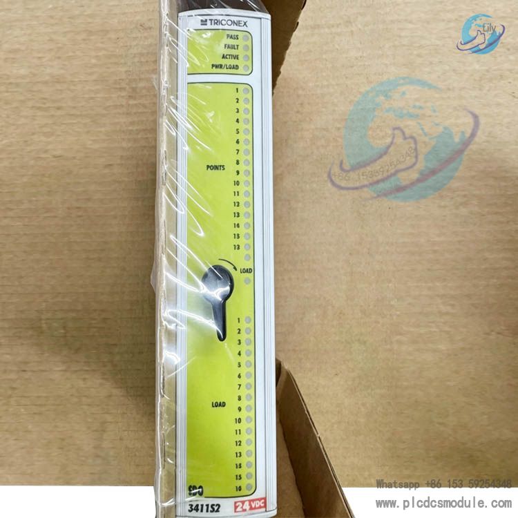
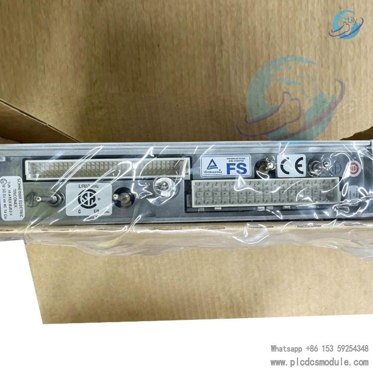
TRICONEX Tri‑GP 3411S2 Digital Output Module|DO3411S2
Product Introduction
TRICONEX 3411S2 (DO3411S2) is a TMR digital output module for the Tri‑GP universal Safety Instrumented System. It is equipped with three sets of independent isolated channel hardware and implements output‑signal voting processing via the patented Quad Voter circuit. Receiving commands from the main processor, DO3411S2 outputs 24 VDC digital switching signals to drive field solenoid valves, relays and audible‑visual alarm devices. Built‑in OVD Output Voting Diagnostic routines maintain safe output capability even under single‑channel faults. It is critical I/O hardware for Tri‑GP systems to implement ESD emergency shutdown and F&G fire‑gas interlock functions. Sharing the same hardware framework with the 3401S2, 3411S2 is specially adapted for minimum field‑load current; load constraints of both models must be distinguished during model selection.

Technical Specifications
| Parameter | TRICONEX 3411S2 (DO3411S2) |
| Channel Count | 16 channels, common‑terminal type |
| Rated Output Voltage | 24 VDC |
| Operating Voltage Range | 19‑30 VDC |
| Absolute Maximum Output Voltage | 45 VDC |
| Maximum Reverse Input Voltage | ‑0.6 VDC |
| Minimum Field‑Load Current | 30 mA |
| Switching Output Current | <4.8 A, typical 3.0 A self‑current‑limiting |
| Continuous Sustained Current | Max 700 mA self‑current‑limiting |
| Field Alarm Detection | Field power loss, output short‑circuit ON / short‑circuit OFF |
| Loop Read‑back Threshold | 0‑5 VDC = OFF range; 6‑14 VDC transition range; 15‑30 VDC ON range |
| Off‑state Leakage Current | <1 mA |
| Diagnostic Glitch Duration | Max <2 ms, typical 500 μs |
| Maximum Switching Rate | >20 ms |
| ON‑state Voltage Drop | <1.6 VDC @1.6 A |
| Full‑16‑point Read‑back Scan Time | <8.0 ms |
| Isolation: Functional Ground to Protective Ground | Minimum 500 VDC |
| Isolation Between Functional Logic Grounds | Minimum 800 VDC |
Core Advantages
- TMR triple‑modular‑redundancy architecture with three independent isolated channels and Quad Voter voting logic. Output action is triggered when two out of three channel commands agree. Multi‑redundant critical signal paths balance safety grade and system availability.
- Periodic automatic OVD Output‑Voting‑Diagnostics detect output‑point sticking, switching‑device and drive‑loop faults. Panel fault LED illuminates and system alarms are triggered upon detection; only the faulty channel is flagged instead of declaring total DO3411S2 module failure.
- Stable operation under single‑fault conditions; output remains available for selected multi‑fault scenarios to reduce unplanned‑shutdown probability.
- Complete loop read‑back mechanism verifies real‑world voltage status on the field‑load side, distinguishing OFF, transition and ON voltage ranges for true actuator‑status feedback.
- Built‑in self‑current‑limiting protection for both switching and continuous output phases, preventing hardware damage caused by field short‑circuits.
Product Features
Every output point on TRICONEX 3411S2 supports continuous full channel‑level diagnostics; faults are isolated to affected channels while remaining points keep working. DO3411S2 enforces a hard 30 mA minimum field‑load requirement. Loops below this threshold trigger abnormal diagnostic alarms — this is the primary difference versus the 3401S2 which imposes no minimum‑load constraint. Diagnostic‑induced pulse glitches are limited to millisecond range and will not cause mis‑operation for most industrial field actuators. DO3411S2 fits Tri‑GP chassis slots and is fully compatible with the complete Tri‑GP controller hardware‑software ecosystem. Fault information can be remotely retrieved and analysed within the TriStation 1131 configuration software. Isolation withstand meets industrial‑safety specifications with functional‑ground‑to‑protective‑ground isolation to suppress field common‑mode interference.
Application Fields
As an output unit for Tri‑GP Safety Instrumented Systems, DO3411S2 serves process‑industry safety‑interlock scenarios. In oil & gas it is deployed within ESD emergency‑shutdown and F&G fire‑gas protection systems to drive shut‑off valves, blow‑down valves and fire‑alarm devices. For chemical plants it implements reactor interlock protection and leak‑isolation output control. Coal‑chemical and power‑plant safety‑interlock loops utilise it for relays, audible‑visual beacons and solenoid‑valve control. It also delivers final‑element drive outputs for HIPPS High‑Integrity‑Pressure‑Protection systems. This module is intended exclusively for safety‑related SIS systems and is not recommended as a general‑purpose DCS discrete‑output card.
Product Comparison (3401S2 VS 3411S2)
| Comparison Item | 3401S2 | 3411S2 (DO3411S2) |
| Channel Count | 16 channels, common‑terminal | 16 channels, common‑terminal |
| Minimum Field‑Load Current | No requirement | 30 mA |
| Absolute Maximum Output Voltage | 33 VDC | 45 VDC |
| ON‑state Voltage Drop | <1.0 VDC @1.5 A | <1.6 VDC @1.6 A |
| Full‑point Read‑back Scan Time | <1.0 ms | <8.0 ms |
| Typical Application | Low‑load, micro‑current field loops | Standard solenoid valves, relays, loop current ≥30 mA |

Compatible Products
- Tri‑GP Main Processor Module: 5101S2
- Tri‑GP Communication Module: 5201S2
- Tri‑GP Power‑Supply Module: 8310S2
- Tri‑GP Main Chassis: 8110S2
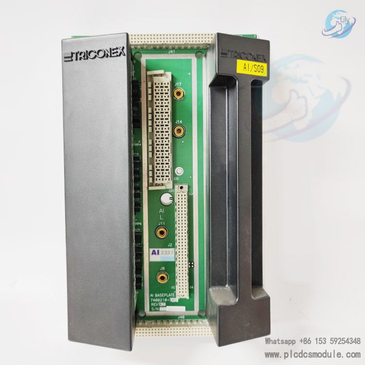
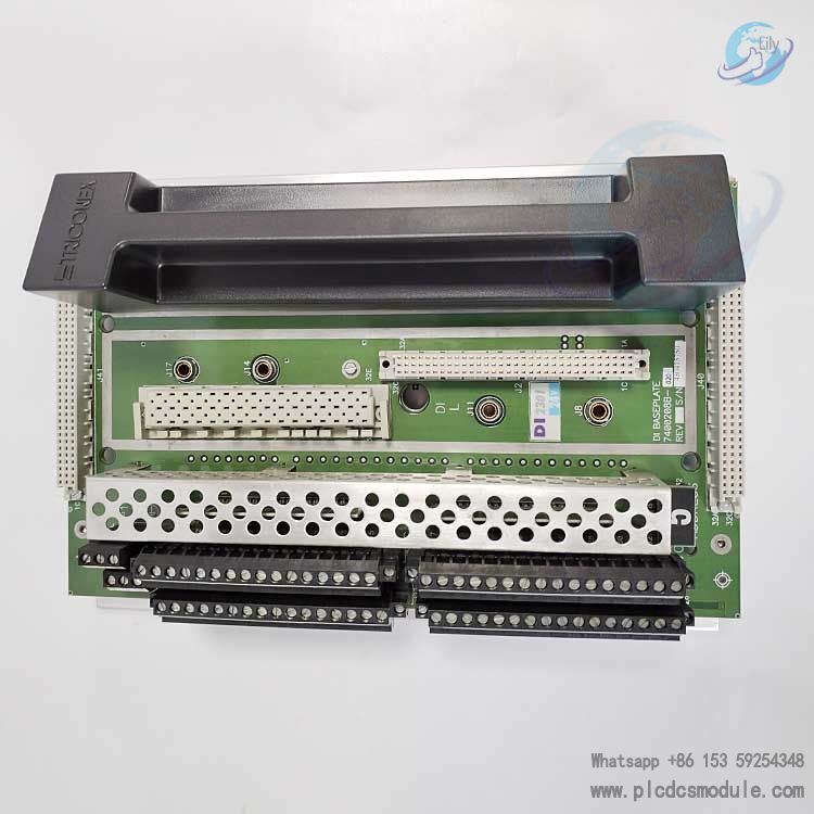
- Matching Terminal Baseplate: TB3400S2
- Configuration Software: TriStation 1131
Note: DO3411S2 must be installed in Tri‑GP‑series chassis slots and requires a corresponding baseplate for field‑cable termination. Full hardware parameter configuration and OVD‑diagnostic enable/disable setup are performed via TriStation 1131.
Recommended Same‑brand Product Models
- 3401S2 Digital Output Module
- 3411S2 Digital Output Module
- 3501S2 Digital Input Module
- 3511S2 Digital Input Module
- 3701S2 Analog Input Module
- 3711S2 Analog Input Module
- 3801S2 Analog Output Module
- 3811S2 Analog Output Module
- 5101S2 Main Processor Module
- 5201S2 Communication Interface Module
- 8310S2 Redundant Power‑Supply Module
- 8110S2 Tri‑GP Main Chassis
- TB3400S2 I/O Terminal Baseplate
- 5301S2 Expansion Interface Module
- 3601S2 Relay Output Module
Notes
- Every output‑channel field loop for DO3411S2 must maintain load‑current ≥30 mA. Insufficient load‑current triggers persistent loop‑fault alarms; switch to 3401S2 for such cases.
- OVD Output‑Voting‑Diagnostics are enabled by default. If temporary OVD deactivation is required for process reasons, modify system properties inside TriStation 1131. OVD must be re‑enabled and run for several minutes every 3‑6 months for circuit self‑testing; permanent OVD disable is prohibited.
- An illuminated fault LED indicates channel‑level faults, not total 3411S2 module failure. Locate exact fault points via software diagnostic panels. Remaining channels can keep running under single‑channel‑fault conditions.
- Observe voltage‑parameter limits strictly; output terminals shall not exceed 45 VDC maximum voltage and reverse voltage shall not exceed ‑0.6 VDC.
- Separate functional‑ground and protective‑ground wiring to preserve isolation‑withstand performance and mitigate field interference.
- Follow the Tri‑GP installation‑planning manual for module‑replacement procedures and verify chassis‑version compatibility to avoid hardware‑version mismatches.
FAQ
Q: Can DO3411S2 and 3401S2 be directly swapped with no restrictions?
A: Direct unconditional replacement is not allowed. DO3411S2 imposes a hard 30 mA minimum‑load requirement; insufficient field‑loop current will trigger continuous loop alarms after replacement. 3401S2 has no minimum‑load constraint. Physically the slots and baseplates are compatible, always verify field‑load‑current parameters during selection.
Q: Does an illuminated Fault LED on 3411S2 mean immediate module replacement is mandatory?
A: No. The Fault LED signals one or multiple channel faults rather than complete DO3411S2 failure. Retrieve diagnostic information from TriStation 1131 to pinpoint faulty channels. Remaining channels remain operational under single‑channel‑fault conditions; replacement can be scheduled for planned downtime instead of emergency shutdown.
Q: Will OVD diagnostics from DO3411S2 cause mis‑operation of field equipment?
A: Diagnostic glitch pulses have a typical value of 500 μs with maximum duration below 2 ms. Most industrial solenoid valves and relays will not respond to such short pulses. For a small number of highly‑sensitive field devices, disable OVD for corresponding points in software, yet manually re‑enable self‑testing periodically.
Q: Can DO3411S2 be used as general‑purpose discrete output within ordinary DCS systems?
A: Not recommended. DO3411S2 is a dedicated TMR I/O card for Tri‑GP Safety Instrumented Systems. It only works paired with Tri‑GP controller hardware and TriStation 1131 software and cannot interface with third‑party generic DCS controllers.
Q: Does purchasing 3411S2 require simultaneous procurement of the TB3400S2 terminal baseplate?
A: The DO3411S2 module is supplied without wiring‑terminal baseplate. New‑build projects shall order TB3400S2 together. Retrofit projects may reuse existing baseplates after confirming compatibility.
Q: What maximum load‑current can DO3411S2 drive?
A: Instantaneous switching peak current <4.8 A (self‑limited). Maximum continuous sustained current is 700 mA. Do not exceed 700 mA long‑term per‑channel rating to avoid module overheating damage.
Q: Field‑wiring is confirmed intact yet 3411S2 persistently reports load fault. What should be checked first?
A: First verify actual loop operating‑current meets the 30 mA minimum‑load threshold. Insufficient load‑current is the most‑common root‑cause for DO3411S2 load‑fault alarms. Replace with 3401S2 when loads are too low.
Q: Are all 16 output points of one DO3411S2 inside Tri‑GP capable of SIL‑rated safety‑functions?
A: All 16 channels support TMR voting and OVD diagnostics. Provided the full Tri‑GP system holds safety certification, every point may be utilised within SIL‑grade safety‑interlock loops.