HIMA X‑DI 64 01 (HIMax) Digital Input Module
Overview
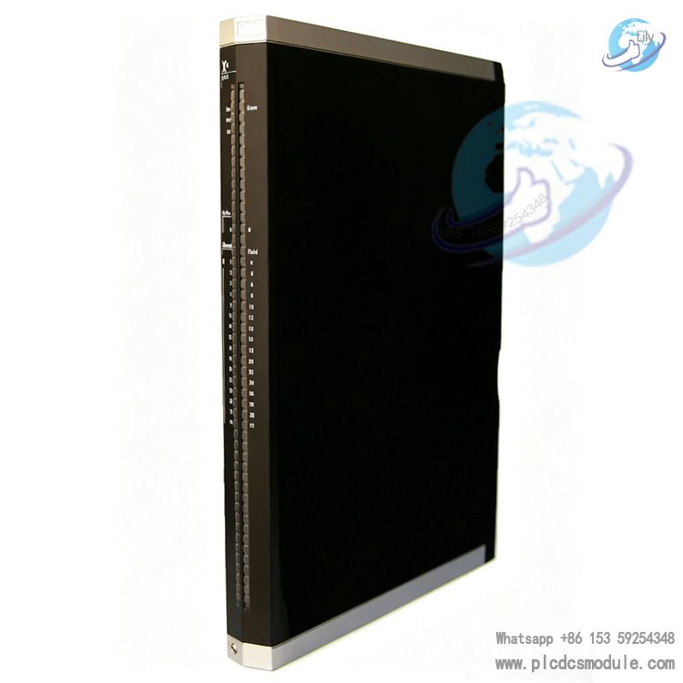
X‑DI 64 01 is a high‑density safety‑oriented digital input module under Germany HIMA HIMax safety control system, developed specifically for Safety Instrumented System (SIS). It provides 64‑channel 24VDC digital input channels, adopts 1oo2 safety processor architecture, and holds TÜV SIL3, PL e, Cat.4 safety certifications. It is used to collect field switch signals such as dry contacts and 2‑wire proximity switches. The module must be used together with X‑CB006 series terminal boards. It supports hot‑swap, channel‑level diagnostics, single/redundant configuration, and is compatible with SILworX engineering software. It is widely applied for signal acquisition in high‑risk industrial safety interlock loops.

Technical Specifications
| Channel Quantity | 64‑channel unipolar digital input, no electrical isolation between channels |
| Input Type | Sink logic, compliant with IEC 61131‑2 Type3 standard, 24VDC signal compatible |
| Module Power Supply | 24VDC, voltage fluctuation range ‑15%~+20%, overall input current 400mA‑1.5A, max. 4mA per channel |
| Grouped Sensor Power Output | 8 groups of short‑circuit‑protected output power S1+~S8+, each group supplies 8 channels, max. output current 100mA per group; undervoltage fault detection below 17VDC |
| Switch Threshold | Typical 9.4V ±0.8V (2.1mA±0.3mA), input operating voltage range ‑3~30V |
| Operating Temperature | 0~+60℃ |
| Storage Temperature | ‑40~+85℃ |
| Pollution Degree | II, applicable altitude <2000m |
| Protection Class | IP20 |
| Weight | Approx. 1.5kg |
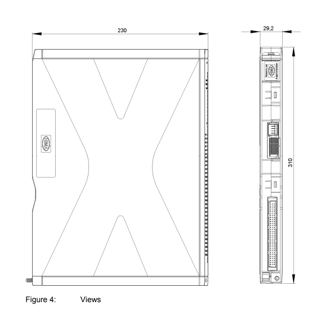
| Dimensions (H×W×D) | 310 × 29.2 × 230 mm |
| Safety Certifications | TÜV SIL3 (IEC61508/IEC61511), Cat.4 (EN954‑1), PL e (EN ISO13849‑1) |
Hardware & Configuration
Hardware must be matched with X‑CB006 series terminal boards, including screw terminal standard type X‑CB006‑01, screw terminal redundant type X‑CB006‑02, cable plug standard type X‑CB006‑03, cable plug redundant type X‑CB006‑04. Hardware version AS10 and above is equipped with mechanical coding to prevent incorrect module insertion. Terminal boards can remain on the rack; only the module body supports hot‑swap without modifying field wiring.
When using cable‑plug‑type terminal boards, X‑CA003 series system cables shall be selected. Cable specification: 80×0.25mm²+2×2×0.25mm², with three standard lengths of 8m, 15m, 30m for interfacing with field FTA terminal assemblies.
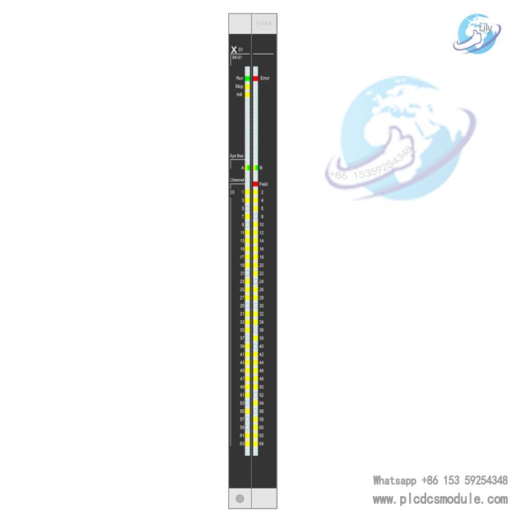
Front‑panel LED indicators are divided into three groups: module status indicators Run, Error, Stop, Init; system bus A/B indicators; I/O channel indicators. Steady yellow channel LED means channel powered on; blinking yellow indicates channel fault; blinking red Field LED denotes over‑current or short‑circuit faults in field loop.
Configuration is completed via SILworX software. Users can set channel OFF delay Toff, Test Suppression, channel power supply enable status, channel redundancy switch. Diagnostic variables including Module Status, Submodule Status, Diagnostic Status, Supply1‑8 OK, Channel OK, Channel Value can be read. Upon module fault, input signals are forced to 0 and enter safe state with red Error LED lit. Built‑in background self‑test realizes channel over‑current shutdown and power‑supply undervoltage monitoring.
Multiple wiring schemes are supported. Single‑module mode accepts 2‑wire proximity switches, dry contacts, externally isolated digital sources and non‑isolated digital sources. Redundant terminal boards enable dual X‑DI 64 01 channel redundant acquisition. For explosion‑proof scenarios, Zener safety barriers or HIMA isolator amplifiers H4011/H4012 shall be externally connected. Unused channels can be left floating without termination. Do not connect wires to terminal boards with field‑side floating to avoid short‑circuit and ignition risks.
Core Advantages
- High Channel Density: Single module delivers 64 safety DI channels occupying only one rack slot, saving cabinet space and reducing overall hardware cost. Ideal for applications requiring massive discrete interlock signal acquisition.
- 1oo2 Dual‑processor Safety Architecture: Meets SIL3 safety level with fail‑to‑safe behavior. Inputs are forced to safe‑0 upon module failure to satisfy strict SIS safety requirements.
- Convenient On‑site Maintenance: Module‑body hot‑swap supported while terminal boards stay on backplane with unchanged field wiring. Online replacement shortens maintenance downtime. Mechanical anti‑mismatch coding prevents wrong installation physically.
- Multi‑level Fine‑grained Diagnostics: Independent fault diagnosis for overall module, 8 power groups and each individual channel. Module temperature, voltage and fault codes are accessible for user program. Panel LEDs help quick on‑site troubleshooting for short‑circuit, over‑current, undervoltage and hardware defects.
- High Configuration Flexibility: Supports single‑module and channel‑redundant operation modes. Channel filter delay and test pulse suppression can be configured for different sensors. Global variable mapping inside SILworX facilitates status reading; fault reset parameters allow module to return to RUN after recovery.
- Diversified Wiring Solutions: Screw‑terminal and cable‑plug terminal board options available with FTA field terminal assemblies. Compatible with safety barriers and isolators for both general plant areas and hazardous explosion‑proof zones.
Application Fields
- Petrochemical SIS safety instrumented systems: ESD emergency shutdown system, safety valve position feedback, interlock switches and fire‑detection switch signal acquisition
- Safety interlock for oil‑gas, coal‑chemical and fine‑chemical plants
- Power‑industry boiler and turbine safety protection systems for interlock contact and limit‑switch collection
- HIMax platform railway safety control systems
- PL e‑rated machinery safety monitoring loops
- Safety monitoring for offshore platforms and tank‑farm high‑risk processes
Explosion‑proof plant zones: collect proximity switch and dry‑contact signals from hazardous areas via safety barriers or isolation amplifiers
FAQ
Q1: Can X‑DI6401 module be directly wired to field signals?
A: No. The module body cannot connect field cables directly. X‑CB006‑series terminal boards are mandatory for field‑signal transition. Standard and redundant versions are selected according to single/redundant schemes.
Q2: Is power‑off required for module hot‑swap? What are hot‑swap restrictions?
A: HIMax system allows module hot‑swap under running status; only module body is inserted/removed while terminal boards remain on rack backplane. Fan cover opening duration shall not exceed 10 minutes to avoid insufficient heat dissipation; fasten cover after replacement. Terminal boards do not support hot‑swap; rack shutdown is required for terminal‑board disassembly.
Q3: Notes for S1+~S8+ grouped power supply usage?
A: Each S+ power group corresponds to fixed channels: S1+ for DI1‑DI8, S2+ for DI9‑DI16 and so on. Wired channels must use power from their corresponding group. If module internal power supply is not used, disable “Sup. used” in SILworX channel parameters; otherwise undervoltage will trigger false channel faults. Each group features short‑circuit protection with max. 100mA output current.
Q4: What does Channel OK = FALSE indicate?
A: It means faults detected on this channel, including over‑current, short‑circuit, power‑supply abnormality or internal hardware failure. Channel Value is forced to 0 upon fault occurrence. Read Diagnostic Status ID for precise fault localization. I/O LED blinks in Blinking2 mode and Field red LED indicates field‑side fault.
Q5: What is the difference between X‑DI6401 and X‑DI6451?
A: X‑DI6401 holds SIL3 safety certification for safety loops. X‑DI6451 is non‑safety version only for ordinary non‑safety signal acquisition and must not be applied in SIS safety interlock loops.
Q6: How to deploy X‑DI6401 in explosion‑proof hazardous areas?
A: Install module body inside safe‑area cabinet. Hazard‑side signals must pass through Zener safety barriers or HIMA isolation amplifiers H4011/H4012. Do not feed hazardous‑zone signals directly into terminal boards; comply strictly with explosion‑proof installation specifications.
Q7: How to handle unused DI channels?
A: Unused channels can stay floating without wiring or resistor termination. Never connect wires to terminal boards while field‑side ends remain floating to prevent short‑circuit and ignition hazards.
Q8: What is channel status after module fault?
A: When internal hardware fault is detected, module enters safe state and all input channels are forced to logic‑0 with red Error LED illuminated, complying with SIL3 fail‑safe principle. Confirm fault default value is configured to 0 in project to guarantee valid safety logic.
Q9: What periodic maintenance is required?
A: According to manuals, Proof‑Test safety verification shall be performed every 10 years. Module firmware can be updated during system downtime window. Defective hardware shall be replaced as a whole; no on‑site repair is allowed and identical spare parts must be adopted.
Q10: How to realize channel redundant acquisition?
A: Adopt X‑CB006‑02 screw‑terminal redundant terminal board or X‑CB006‑04 cable‑plug redundant terminal board. Insert two X‑DI6401 modules into rack slots and activate Redund. option for target channels inside SILworX to achieve dual‑module acquisition and voting for single field signal and improve system availability.
Related Matching Products
X‑DI6401 body cannot connect field cables directly; X‑CB006‑series terminal boards mounted on X‑BASE rack backplane are mandatory I/O transition accessories.
- X‑CB 006 01: Screw‑terminal standard terminal board for single‑module scheme; field cables are crimped directly without redundancy function.
- X‑CB 006 02: Screw‑terminal redundant terminal board supporting dual X‑DI6401 channel‑redundant acquisition for dual‑module input voting on one field signal.
- X‑CB 006 03: Cable‑plug standard terminal board for single‑module application, connected to external FTA field terminal assemblies via X‑CA003 system cables.
- X‑CB 006 04: Cable‑plug redundant terminal board for redundant mode, connecting FTA assemblies via system cables to complete dual‑module channel redundancy.
Hardware version AS10 and above features mechanical anti‑mismatch coding exclusively for X‑DI6401; mixing with other I/O series is prohibited.
System connection cables match X‑CB006‑03 and X‑CB006‑04: X‑CA 003 01‑8 (8m), X‑CA 003 01‑15 (15m), X‑CA 003 01‑30 (30m). Cable specification: 80×0.25mm²+2×2×0.25mm² with coded plugs on both ends for linking X‑CB006 terminal boards and X‑FTA field terminal assemblies.
Field Terminal Assembly (FTA) is optional: X‑FTA 003 02 FTA terminal assembly supports DIN‑rail mounting. Sensors and switches are wired on FTA side and connected to X‑CB006 through X‑CA003 cables, suitable for large‑scale cabinet wiring grouping.
Rack and core system hardware are HIMax platform fundamentals:
- X‑BASE series: HIMax rack backplane for mounting CPU, X‑SB01, terminal boards and I/O modules, providing system bus and power loops.
- X‑SB 01 system bus module: Minimum 2 pieces for redundancy, delivering redundant system‑bus communication for I/O modules; X‑DI6401 exchanges data with CPU via X‑SB01.
- X‑CPU 01 high‑performance processor module: For large‑scale projects to execute safety user programs.
- X‑CPU 31 compact processor module: Cost‑optimized for medium‑and‑small‑size SIS projects.
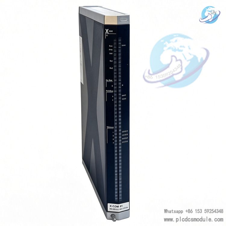
- X‑COM 01 communication module: Data exchange with third‑party PLC, SCADA and HMI.
Explosion‑proof optional accessories for hazardous‑zone deployment: H4011, H4012 HIMA isolation amplifiers for intrinsically‑safe loops to isolate hazardous‑area DI signals while X‑DI6401 resides in safe‑area cabinet; MTL7787+, Pepperl+Fuchs Z787 Zener safety barriers for intrinsic‑safe circuits together with X‑DI6401 for Ex‑rated signal acquisition with module installed inside safe cabinet.
Engineering software: SILworX V4 or higher for HIMax engineering configuration, parameter setting, diagnostic reading and firmware download. All X‑DI6401 module configuration, channel parameter setup and fault diagnosis are implemented within this software.
Peer Product Comparison
HIMA HIMax digital input modules are divided into safety versions (suffix ‑0X for SIS safety interlock) and non‑safety ordinary versions (suffix ‑51 only for general signal acquisition, forbidden for safety loops).
- X‑DI 64 01: 64‑channel 24VDC sink‑input, SIL3, PL e, Cat.4 certified, 1oo2 safety architecture, independent channel diagnostics, channel redundancy function, 8 groups of built‑in sensor power supply, requires X‑CB006 terminal boards. Major strength: high‑density 64‑channel per slot for massive safety discrete‑signal acquisition such as ESD valve feedback and interlock dry contacts to save rack slots. Limitations: no hardware SOE function; only 24VDC input supported; max. 100mA per built‑in power group. External power supply is required when sensor current is high.
- X‑DI 64 51: Identical mechanical outline and channel quantity/circuitry as X‑DI 64 01, without safety certifications. Only for ordinary non‑safety discrete‑signal acquisition; strictly prohibited for SIS safety interlock.
- X‑DI 32 01: 32‑channel 24VDC safety DI, SIL3/PL e rating, matched with X‑CB001 terminal board. Lower channel density than X‑DI6401 yet superior per‑channel load capacity, suitable for safety projects with moderate DI point count.
- X‑DI 32 02: 32‑channel SIL3‑certified DI with 8.2VDC input dedicated for intrinsically‑safe 2‑wire proximity switches with loop‑wire‑break monitoring, paired with X‑CB002 terminal board. Widely used for heavy‑duty 2‑wire proximity‑switch safety acquisition in explosion‑proof zones.
- X‑DI 32 03: 32‑channel SIL3 safety DI supporting 48VDC input, matched with X‑CB003 terminal board for field‑loop 48VDC safety switch‑signal scenarios.
- X‑DI 32 04: 32‑channel 24VDC SIL3 safety DI with X‑CB001 terminal board. Highlight: hardware‑level SOE sequence‑of‑event recording with millisecond‑level event capture for SIS ESD accident traceability. Select X‑DI3204 if SOE function is required instead of X‑DI6401.
- X‑DI 16 01: 16‑channel 120VAC safety DI with SIL3 certification, matched with X‑CB004 terminal board for 120VAC safety contact‑signal collection.
Selection Tips
- X‑DI6401 exclusively uses X‑CB006 terminal boards. Mixing with X‑DI32‑series modules is prohibited. Hardware version AS10 and above features physical anti‑insertion‑error coding.
- X‑DI6401 has no hardware SOE capability; only user‑program cycle time serves as time stamp. Choose X‑DI3204 when SOE accident‑recording function is demanded.
- For redundant hardware solution, deploy X‑CB006‑02 or X‑CB006‑04 redundant terminal boards and activate Redund. channel option inside SILworX software.
Built‑in S1+~S8+ grouped power supplies correspond to fixed channels; cross‑group power mixing is forbidden. When total sensor current of one group exceeds 100mA, external 24V power supply must be adopted and corresponding power‑supply parameter shall be disabled in channel configuration.
Product Tags: