Woodward 9906‑619 (723PLUS) Digital Controller
Overview
The 9906‑619 is the low-voltage version of Woodward 723PLUS series digital speed controller. Hardware manual No. 02877 (Revision H, 2010‑03). It is designed for prime movers such as engines and gas turbines to provide speed regulation and unit load sharing control, widely used in power generation, marine, and industrial prime mover speed governing applications. The same series also includes high-voltage model 9906‑620 and special filtering version 9906‑700.
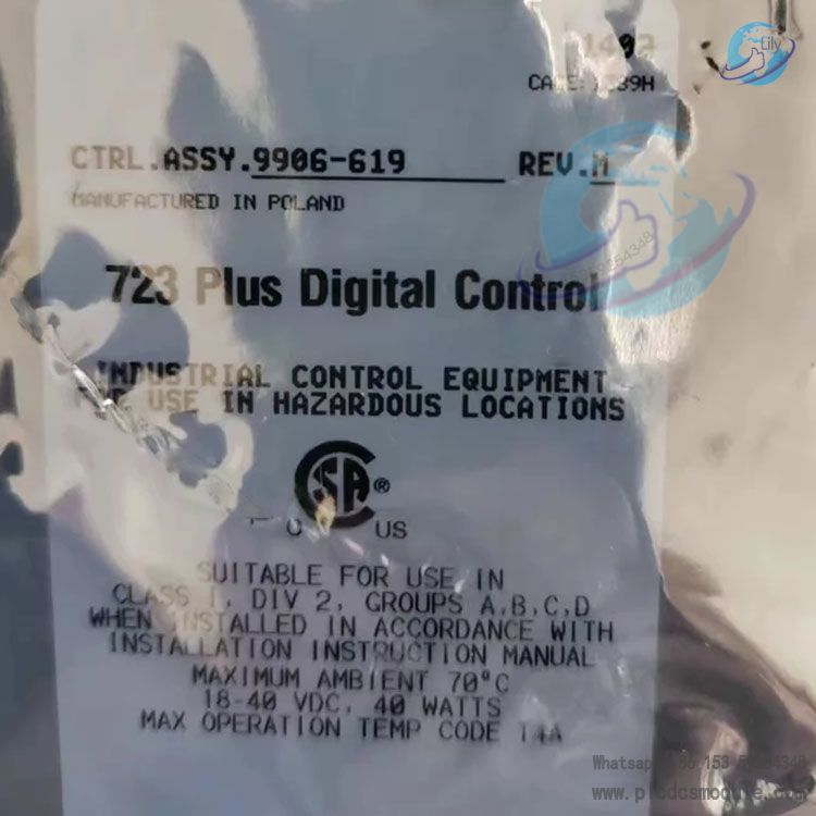
Hardware Structure & Power Supply Parameters
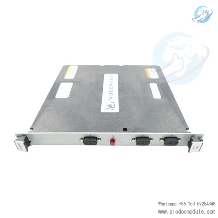
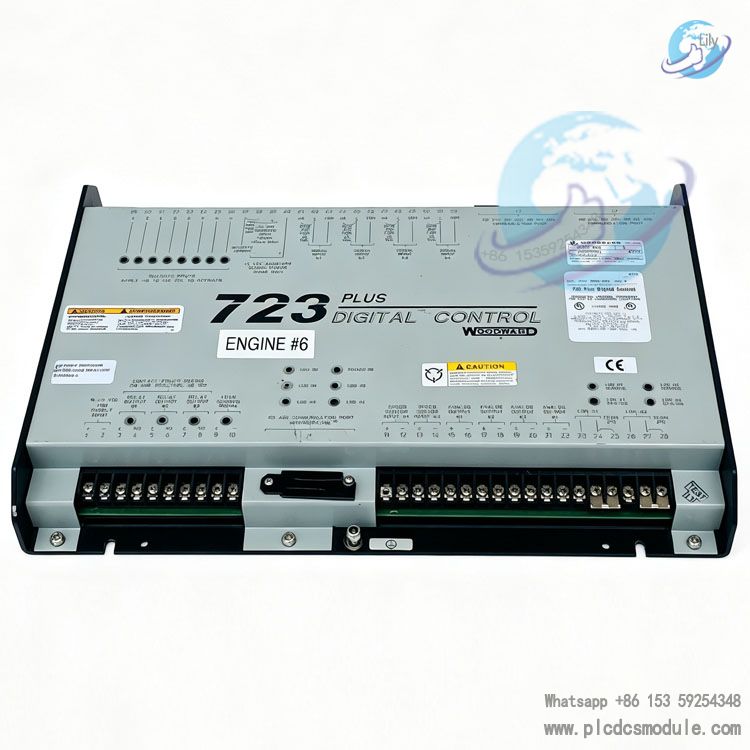
Hardware body: Single PCB board mounted inside a sheet metal enclosure; external interfaces include 3 sets of terminal blocks + 3 pieces of 9-pin D-Sub communication ports (J1/J2/J3). There are 10 internal 2-position jumpers (JPR series) on the board. Jumpers can be used to configure analog output range, actuator output mode, speed sensor type (magnetic pickup / proximity switch).
Power supply specification (low-voltage type 9906‑619)
Operating voltage: 18‑40 VDC, nominal 24 VDC /32 VDC
Rated power consumption: 40W
Surge inrush current: 7A at 0.1ms; 22A at 15ms
Note: Do not supply power in series with resistors or Zener diodes. The power source shall have low impedance. Battery power supply with charger is preferred. It is forbidden to directly use power supply for high-voltage model on this low-voltage controller.
I/O Interface Resources (All functions can be assigned via software programming)
| Type | Channel Quantity | Key Description |
| Speed Input | 2 channels | Support magnetic pickup MPU (400Hz‑15kHz), proximity switch (30Hz‑15kHz), with torsional vibration filtering. Proximity switch is not recommended for EU compliance projects; input voltage 1‑50Vrms |
| Analog Input | 4 channels | Support ±5VDC or 0‑20mA signal; full scale accuracy 0.5%; non-isolated. Current loop isolator is recommended for common-ground systems |
| Analog Output | 2 instrument outputs + 2 actuator outputs | Instrument: 0‑1mA /4‑20mA; Actuator: 0‑20mA, 0‑200mA single output, 0‑160mA tandem output; range switched via on-board jumpers |
| Discrete Input | 8 channels | Rated 24VDC, 10mA per channel, response time 10ms; can use controller built-in auxiliary 24V power or external power supply |
| Relay Output | 3 channels | Contact rating: 2A@28VDC resistive load; 0.75A inductive load; for alarm, circuit breaker, shutdown and other logic outputs |
| Load Sharing Interface | 1 set of terminals | Support parallel connection of multiple 723PLUS controllers to realize generator set load sharing / droop operation |
| LON Channel | 2 channels | Connect to LonTalk/LinkNet remote I/O node expansion system signal points |
Communication Capability
J1 port: For handheld programmer (9907‑205) commissioning;
J2, J3 serial ports: Configurable via software as RS‑232 / RS‑422 / RS‑485, support Modbus‑RTU / Modbus‑ASCII protocol;
Communication cable requirement: Shielded twisted pair. Terminating resistors shall be fitted at both ends of RS422/485 bus; maximum RS‑485 cable length 4000 feet; maximum RS‑232 cable length 50 feet.
Commissioning & Configuration Methods
Handheld Programmer (9907‑205): Connect to J1 interface. It has two groups of menus:
Service menu: Unit runtime monitoring and fine-tuning of parameters;
Configure menu: Must stop the unit and disable I/O before entering, for modifying hardware and logic configuration parameters. Parameters are saved to EEPROM and will not be lost after power-off.
PC Software Servlink + Watch Window
Connect PC to controller through dedicated cable; support online variable monitoring, parameter reading and writing;
Support firmware download, and save full configuration of one controller as a file for batch download and replication to other identical 723PLUS devices. The prime mover must be stopped before firmware download to prevent overspeed risk.
Environmental Performance & Certifications
Environmental Conditions
Operating temperature: ‑40℃ ~ +70℃; Storage temperature: ‑55℃ ~ +105℃;
Humidity: 95% (20‑55℃); meet marine classification society vibration, shock and EMC electromagnetic compatibility tests. Do not mount directly on prime mover body; install in independent cabinet with good ventilation and heat dissipation, keep away from strong electromagnetic interference sources.
Certifications
CSA certification: Class I Div2 hazardous location (Group A/B/C/D, T4A, 70℃);
CE: compliant with EMC Directive 2004/108/EC, Low Voltage Directive 2006/95/EC;
Marine Classification Society: ABS, BV, DNV, GL, LR, NKK, RINA marine type approval (low voltage version 9906‑619 qualified), complying with marine “Marine Notch” RF suppression installation requirements.
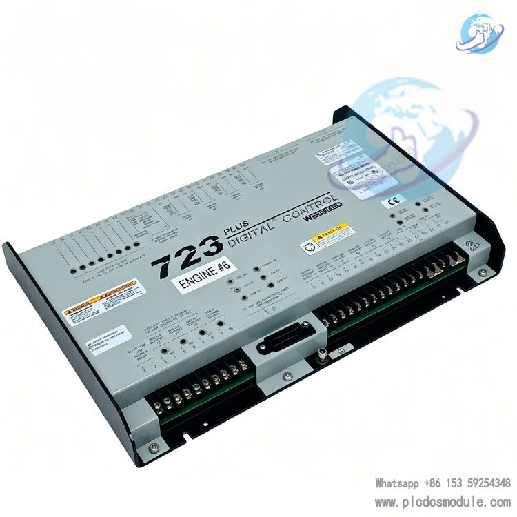
Typical Application & Optional Accessories
Applications
Speed governing for diesel / gas generator set single unit, multi-unit parallel load sharing and droop control;
Marine prime mover speed governing; industrial gas turbine driven equipment; support torsional vibration filtering. Can be matched with synchronizer to realize generator grid connection control.
Optional Accessories
Handheld Programmer 9907‑205;
SPM‑A synchronizer, DSLC digital synchronous load controller;
Active power transducer, power output transducer, rack position transducer;
LinkNet remote I/O expansion node, load pulse unit to expand system capability.
Important Safety Notes
The controller cannot replace independent overspeed shutdown protection device. The system must be equipped with a complete overspeed, overtemperature and overpressure shutdown mechanism fully independent of 723PLUS to prevent runaway and personal & equipment accidents;
ESD anti-static protection must be implemented when disassembling and assembling the controller. Do not touch components on bare PCB with bare hands;
After power on, wait for self-test completion (POWER AND CPU OK green light on), wait at least 60 seconds before starting the prime mover;
All shielded cables shall be grounded to controller enclosure at one end only, the other end shall be insulated and floating to avoid ground loop interference. Isolation amplifier / current isolator is recommended for non-isolated analog loops.
FAQ
Q: Controller restarts repeatedly after power-on?
A: 9906‑619 requires 18‑40 VDC power supply with low impedance. Do not use resistor + Zener diode for voltage reduction. Voltage shall not drop below 18 VDC at startup; wait for green light after power on and wait at least 60 seconds before starting prime mover.
Q: Configuration lost after parameter modification and power cycle?
A: Execute SAVE to write parameters into EEPROM after modification. Direct power-off without saving will roll back parameters to last saved setting, this is not hardware failure.
Q: Choose magnetic pickup MPU or proximity switch for speed sensor?
A: Magnetic pickup MPU is factory default. On-board jumper needs to be changed for proximity switch. Proximity switch is not recommended for EU‑CE compliance projects. Gear gap for MPU shall be controlled at 0.25‑1.25 mm.
Q: When to remove jumper for discrete input terminals 37‑38?
A: Keep jumper when using controller built-in 24V auxiliary power; remove jumper when using external 24V power, connect negative of external power to terminal 37. The built-in auxiliary power cannot drive other external devices.
Q: Analog signal fluctuates unstable?
A: Native analog I/O has no galvanic isolation. 20mA current loop isolator is required for common-ground system. Use shielded twisted pair with shield grounded only at controller end and remote end floating; route signal cables away from power cables.
Q: What is difference between Service menu and Configure menu?
A: Service menu can be operated while engine is running for fine-tuning operating parameters; Configure menu can only be entered after unit shutdown and I/O disabled for hardware configuration modification. Entering during running will cause unit shutdown.
Q: RS‑485 communication garbled or intermittent?
A: 100‑120Ω terminating resistors must be fitted at both ends of RS‑485 bus. Use shielded twisted pair, add separate signal ground, shield layer grounded at single end only.