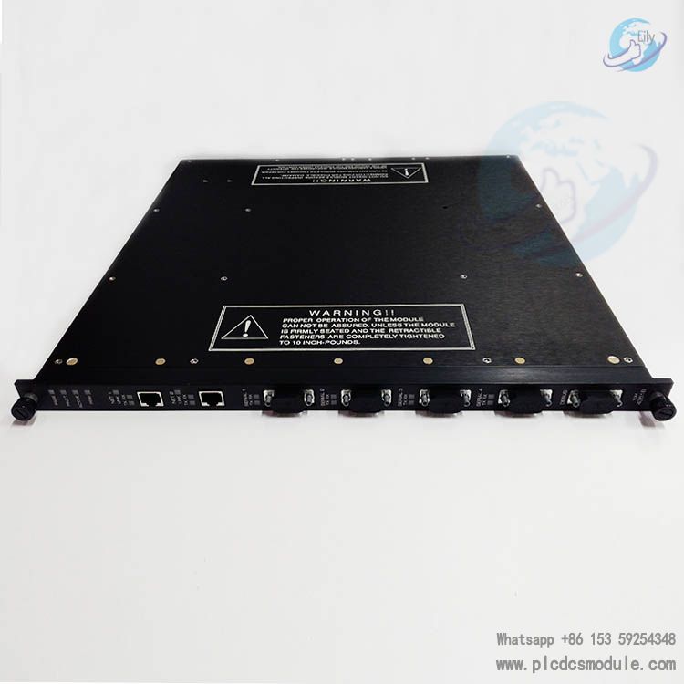


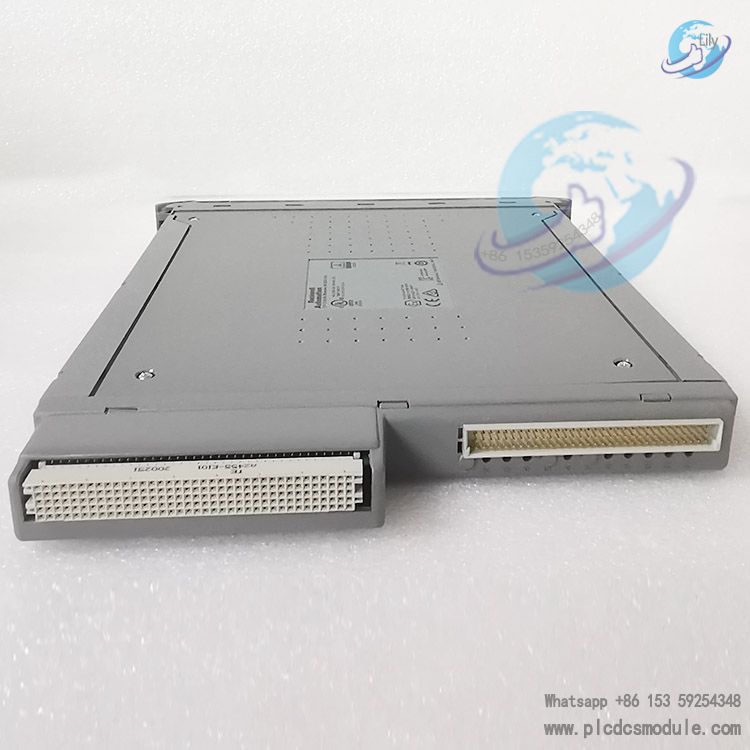
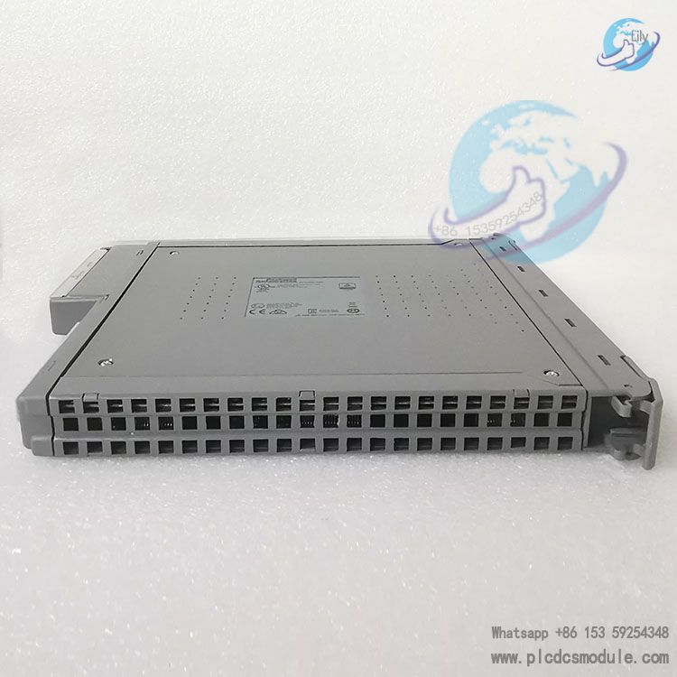
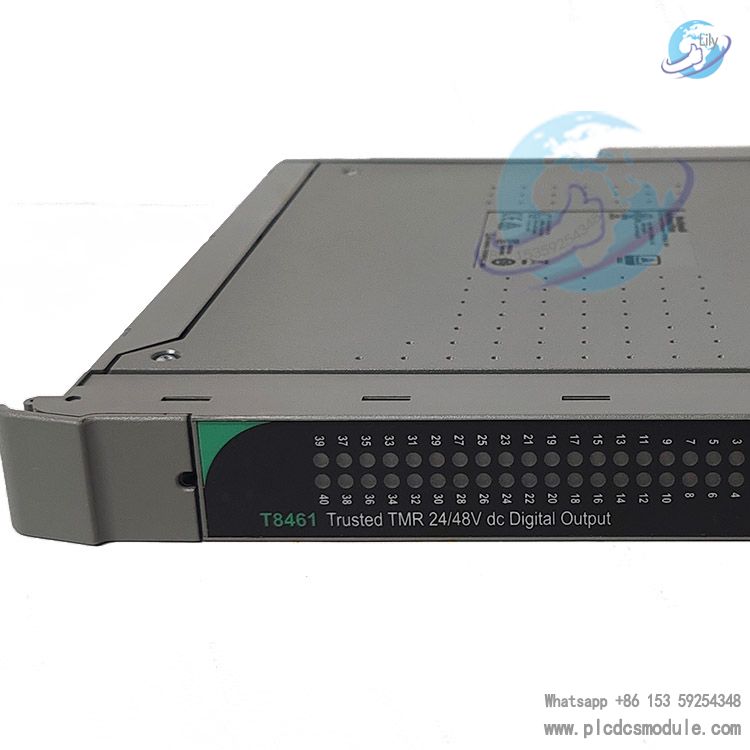
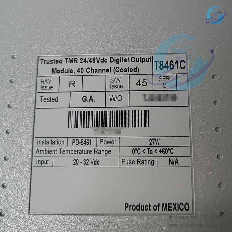
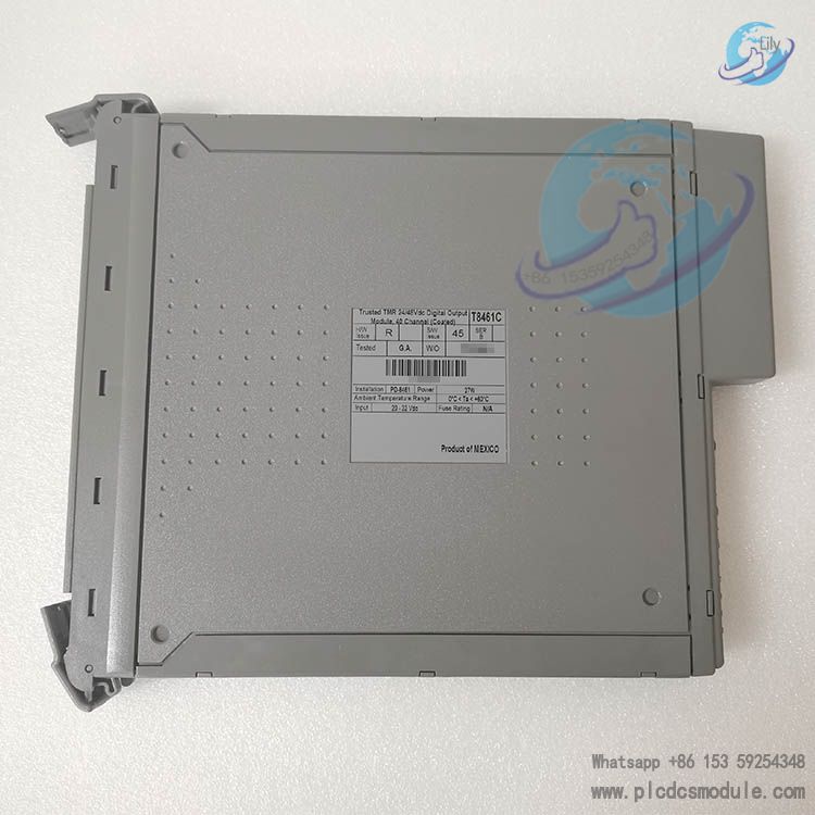
ICS TRIPLEX T8461C Trusted TMR 24/48V DC 40 Channel Digital Output Module
Product Introduction
T8461C is a triple modular redundant (TMR, 2-out-of-3) high-density safety digital output module under Rockwell Trusted T8000 Safety Instrumented System (SIS). Deployed within SIS, it outputs 24 V DC/48 V DC signals to drive solenoid valves, relays and other field actuators. It holds TÜV IEC 61508 SIL 3 safety certification and is widely used for ESD emergency shutdown and FGS fire & gas interlock safety applications in petrochemical, oil & gas, and thermal power industries.
This module cannot directly connect equipment located in explosive hazardous areas and must be used with intrinsic safety barriers. The suffix C denotes the conformal coated version, suitable for cabinet environments with high humidity and corrosive gases. Its electrical and logical functions are fully identical to T8461.
Download

1. Hardware Architecture
The module consists of four major functional units. Slices A/B/C are mutually isolated; failure of one slice will not disrupt operation of the remaining slices.
- HIU Host Interface Unit: Interfaces with the backplane IMB inter-module bus to communicate with the TMR processor. It contains three isolated fault containment regions (FCR) for A/B/C slices, performing 2-out-of-3 voting, local DSP diagnostics, redundant power supply, and outputting isolated serial links to FIU.
- FIU Field Interface Unit: 3 sets corresponding to the three slices respectively, integrating output switches and Σ‑Δ sampling circuits to measure output voltage and current and execute on-line diagnostics of MOSFET switches.
- FTU Field Terminal Unit: Integrated group fault safe switch (GFSS), EMI filtering and overvoltage protection for connection to external field cables. It provides SmartSlot hot standby links for coordinated switchover between primary and standby modules. The 40 output channels are divided into 5 power groups with 8 channels per group. Each group has an independent GFSS. In case of multiple module faults, all outputs of the corresponding group will be cut off to achieve fail-safe state.
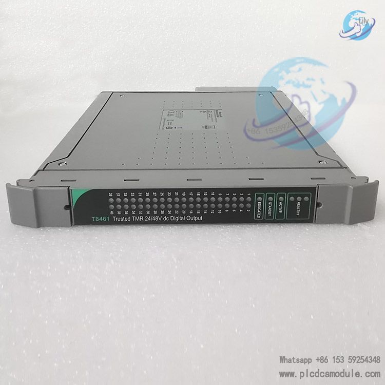
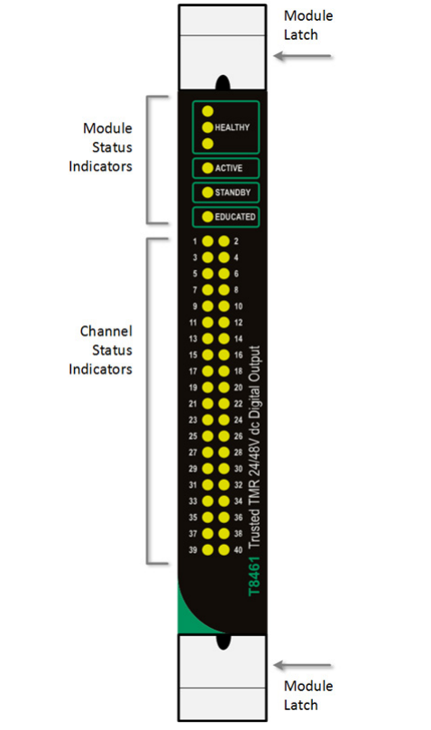
- FPU Front Panel Unit: Equipped with LED status indicators and module extraction latches. It displays device status after 2-out-of-3 voting of signals from the three slices.
The outputs adopt TMR redundant MOSFET switch topology. Each channel is controlled by multiple switches from the 3 slices. Even if one slice fails completely, the remaining two slices can still drive the load. On-line detection of switch stuck‑on / stuck‑off faults is supported without interrupting load power supply during diagnostics.
2. Core Functions
40 triplicated output channels, continuous current per channel: 0.75A; backplane IMB power supply: 20‑32 V DC; field power supply range: 18‑58 V DC.
Channel-level loop real-time monitoring: collects voltage and current to automatically identify open circuit, short circuit and no field power supply faults, and outputs numeric status codes and boolean line fault signals. For unused channels, it is recommended to connect a 10kΩ/0.5W dummy load resistor to 0V to avoid no-load open circuit alarms.
| STATE | Numeric Channel Status | LINE_FLT | Fault Bit |
| 1 | No field supply voltage | 1 | |
| 2 | Output OFF | 0 | |
| 3 | No load / field open circuit | 1 | |
| 4 | Output ON | 0 | |
| 5 | Field short circuit | 1 |
On-board SOE sequence of event recording, time resolution: 1 ms, timestamp accuracy ±10 ms. Channel status changes are automatically timestamped and uploaded to the processor for incident root cause analysis.
Electronic short-circuit overcurrent protection on board; external fuses are not required. Short-circuit faults are latched and can be cleared via system fault reset button or output command toggle. A non-replaceable built-in fuse serves as ultimate hardware protection; module replacement is mandatory once blown.
Hot-swap module replacement without system shutdown supported. Two hot standby architectures:
- Companion Slot: One-to-one dedicated standby slot with dual-width cable, automatic switchover upon fault, consumes more rack slots.
- SmartSlot: Multiple primary modules share one standby slot to save rack space. Cross-cabinet deployment requires rack version V2 or above with TC‑006 cable.
Isolation capability: 2500V impulse withstand opto-magnetic isolation barrier; reinforced insulation isolation of 50V between power groups.
Comprehensive self-diagnostics: monitors board temperature, power supply voltages and switch characteristics, executes safety layer tests (SLT) and Flash CRC verification. Fault information is uploaded to the control system via front panel LEDs, HKEEPING and INFO diagnostic registers.
3. Front Panel Status Indicators
Module Status LEDs
Includes 3 slice Healthy LEDs, Active primary module LED, Standby standby module LED, Educated configuration loading LED.
- Normal operation: All three Healthy LEDs are green.
- Single slice fault: Corresponding Healthy LED flashes red; system can continue running, module inspection and replacement are recommended.
- Critical slice fault: Corresponding Healthy LED stays solid red. Active/Standby indicates the current operating role of the module; Educated indicates whether the module has completed system configuration download.
40 channel two-color LEDs (factory default configuration, customizable via System.INI)
| LED Status | Meaning |
| Off | Output OFF |
| Solid green | Output ON |
| Green flashing | No load / field open circuit |
| Solid red | Short circuit, overcurrent protection latched and output disabled |
| Red flashing | Channel fault / no field supply voltage |
4. Software Configuration
No DIP switches on the module. All configuration is completed in the IEC 61131 toolset on the engineering station. The project is downloaded to the TMR processor which automatically configures the module. The module defines 8 logical Racks:
| Rack | Name | Function Description |
| Rack1 | DO | 40-channel output logic control, boolean output |
| Rack2 | STATE | 40-channel integer status codes for feedback of operating / fault status |
| Rack3 | AI | 40-channel output voltage sampling, unit: 1/500 V; Actual voltage = read value ÷500 (V) |
| Rack4 | CI | 40-channel output current sampling, unit: 1/1000 A; Actual current = read value ÷1000 (A) |
| Rack5 | LINE_FLT | 40-channel boolean line fault alarm signals |
| Rack6 | DISCREP | 3-slice channel voting mismatch status word |
| Rack7 | HKEEPING | Maintenance diagnostic registers: temperature, power supply voltages, fault codes; returns all zeros upon critical slice fault, not for interlock logic |
| Rack8 | INFO | Primary/standby slot status, module health, FCR fault status and other module information |
SOE event recording can be enabled for boolean variables: open variable extended properties in the data dictionary editor, check Sequence of Events, and read event logs via Trusted SOE&Process Historian software.
Main Technical Specifications
| Item | Parameter |
| Output channels | 40 channels, divided into 5 power groups, 8 channels per group |
| Continuous current per channel | 0.75 A |
| Backplane IMB power supply | 20‑32 V DC, power consumption 26 W |
| Field power supply | 18‑58 V DC, maximum total field current of module: 30A |
| SOE resolution | 1 ms, timestamp accuracy ±10 ms |
| Operating temperature | 0 ℃~+60 ℃; Storage temperature:‑25 ℃~+70 ℃ |
| Relative humidity | 10‑95%, non-condensing |
| Safety certification | TÜV IEC 61508 SIL 3 |
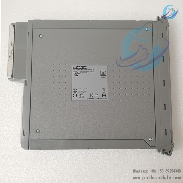
| Dimensions | 266 mm(H) ×31 mm(W) ×303 mm(D) |
| Weight | 1.3 kg |
6. Installation & Maintenance Notes
This module is an electrostatic sensitive device. Wear an anti-static wristband during handling. Do not touch connector pins and do not disassemble the module housing.
Key pins 1,5,7 need to be removed for T8461 matching cables. Do not force insert the module during installation; check for bent backplane pins if resistance is encountered.
Do not directly extract an active primary module; complete primary-standby switchover procedure first.
Cold Start phenomenon: All three Healthy LEDs turn red, Active/Standby LEDs flash red, Educated LED flashes amber. This happens when the module detects ≥2 faults and triggers a safe shutdown. Recovery steps: pull out and reinsert the module. After module completes Educated state, press the TMR processor reset button to re-enable outputs.
Faults are classified as external field faults (short circuit, open circuit, resolve the field loop) and module hardware faults. Under TMR architecture, single slice fault allows continuous system operation but maintenance should be performed promptly. Persistent DISCREP channel mismatch alarm indicates module hardware fault and replacement is recommended.
The overall SIL level of the whole system is determined collectively by the complete system (processor, I/O, logic program, field equipment, maintenance MTTR), and cannot rely solely on the module SIL3 certification.
Related Supporting Products
T8461C belongs to Rockwell‑ICS Trusted T800 safety system, can only be used within T8000 platform and cannot be mixed across series.
- Racks: T8100 (controller rack), T8300 (IO expansion rack); SmartSlot cross-cabinet application requires rack version V2 or above.
- Processor Modules: T8110B / T8111B / T8112B, firmware Trusted Release4.0 or higher.
- Rack Power Supplies: T8200, T8201 series rack power supplies for backplane IMB bus power supply.
- Special IO Cables: TC200: Companion Slot dual-width cable; TC500: SmartSlot single-width cable; TC‑308‑02, TC‑006: SmartSlot jumper and cross-cabinet connection cables.
- Field Terminals: FTA/VFTA field terminal assemblies, cable specification: 0.5 mm² multi-core.
- Explosion-proof Accessories: Intrinsic safety barriers (mandatory for hazardous area field applications).
- Software Tools: Trusted Toolset Suite (IEC61131 toolset for logic configuration and module setup); Trusted SOE & Process Historian (SOE event reading and analysis).
Other IO Modules: Other Trusted TMR I/O modules can be mixed in the same rack, such as T8403, T8424 digital input modules, T8431, T8442 analog input modules.
FAQ
Q1: Can T8461C directly connect field equipment in explosive hazardous areas?
No. The module itself has no explosion-proof certification. Intrinsic safety barriers must be equipped for hazardous area applications.
Q2: Unused output channels frequently report open circuit faults, how to resolve?
The minimum loop monitoring load current of the module is 25 mA. Set the channel output command to OFF in the program and connect a 10kΩ, 0.5W resistor from the terminal to 0V to eliminate no-load alarms.
Q3: One of the Healthy LEDs flashes red, can the system keep running?
Operation can continue. Under TMR 2-out-of-3 architecture, single slice fault does not affect output control. The fault source needs to be checked, and module replacement is recommended if hardware fault is confirmed.
Q4: How to reset a latched short circuit fault on channel?
Eliminate the short circuit fault on field side first. The latched fault can be cleared by pressing the system fault reset button or toggling the channel output command (ON-OFF).
Q5: What are the differences between Companion Slot and SmartSlot hot standby solutions?
Companion Slot adopts one-to-one dedicated standby slot with automatic switchover on fault and consumes more rack slots. SmartSlot allows multiple primary modules to share one standby module to save rack space. Cross-cabinet deployment requires V2 version rack and TC‑006 cable.
Q6: How to convert the physical value from Rack3 voltage and Rack4 current registers?
Actual voltage = AI register value ÷500 (V); Actual current = CI register value ÷1000 (A).
Q7: What is module Cold Start phenomenon and how to recover?
Phenomenon: All three Healthy LEDs turn red, Active/Standby LEDs flash red, Educated LED flashes amber. The module triggers safe shutdown when detecting 2 or more faults. Pull out and reinsert the module. After module completes Educated state, press processor reset button to activate outputs.
Q8: Output command is ON but field load does not act, troubleshooting steps?
① Read STATE status code from Rack2 to confirm fault code;
② Verify field power supply;
③ Read Rack3 voltage and Rack4 current to judge loop condition;
④ Confirm whether the load meets minimum 25mA load requirement;
⑤ Check if short circuit latch exists and perform reset;
⑥ Check whether GFSS of corresponding power group has tripped.