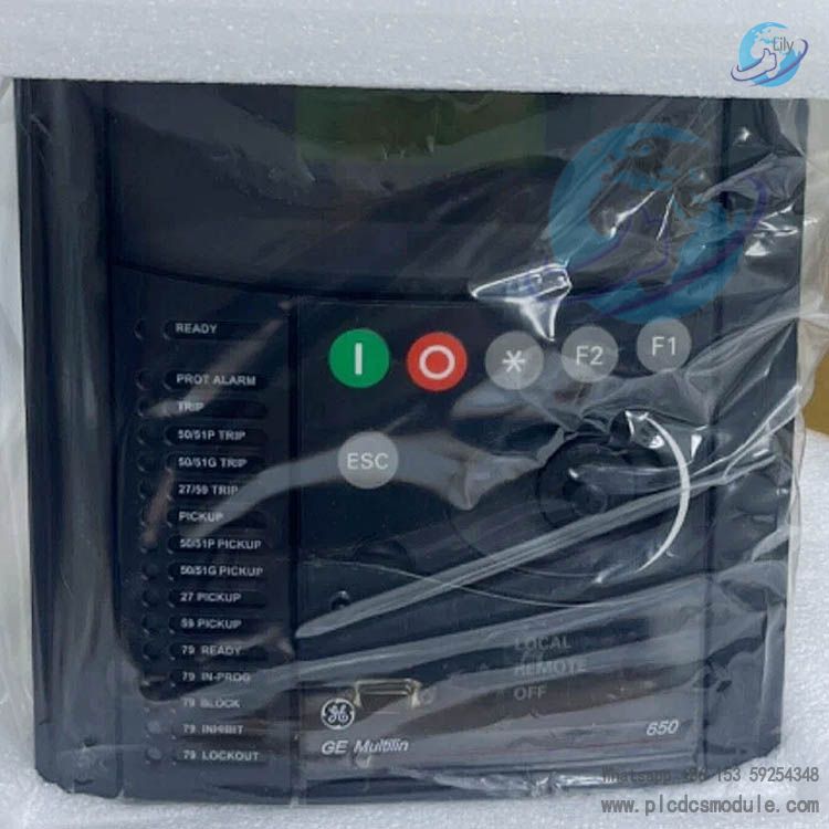
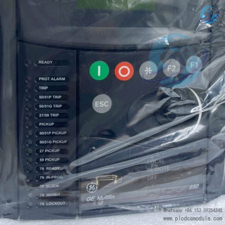
GE Vernova Multilin F650 model F650BABF2G0HI is a standard digital bay controller built on the GE Vernova Multilin F650 platform. It is an integrated protection, measurement and control device for medium-voltage distribution feeders, with three core functions: local bay-level monitoring, circuit breaker logic control, and fast full-line fault protection.
This model adopts a draw-out modular hardware architecture, integrating high-precision analog acquisition, programmable logic controller (PLC), and multi-protocol industrial communication unit. Compatible with multiple primary electrical connection schemes including single busbar, double circuit breaker, 3/2 breaker configuration and ring main unit (RMU), it can serve as the primary protection for distribution feeders and backup protection for transformers, busbars and motors. It is widely applied in new energy stations, industrial and mining enterprises, rail transit, and automation retrofitting projects of municipal substations.
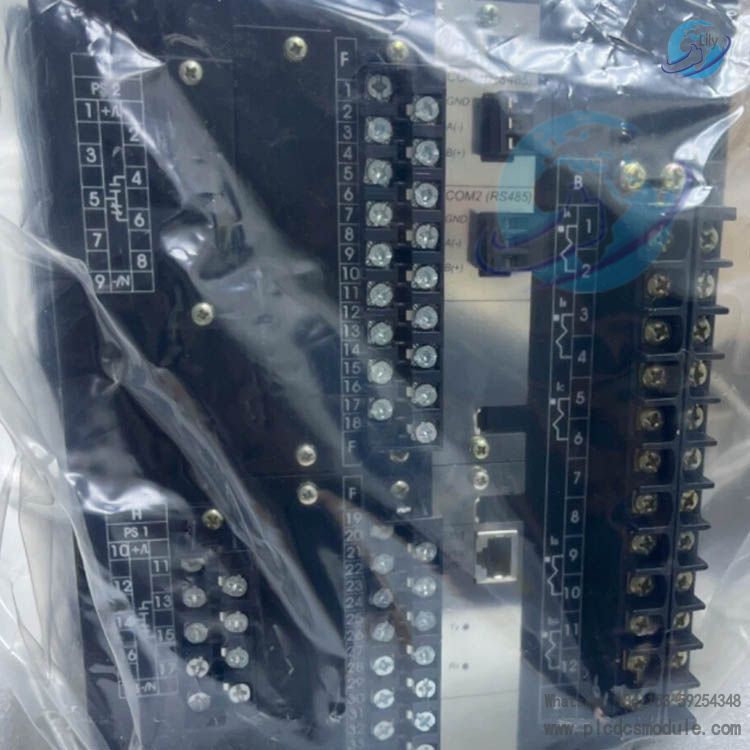
The F650BABF2G0HI comes standard with a basic monochrome display panel, dual redundant RS485 serial ports and 100 Mbps Ethernet communication board. It is equipped with a base I/O module featuring 16 digital inputs and 8 digital outputs, without an expanded I/O board for Slot G. The auxiliary power supply supports a wide voltage range of 110–250 VDC / 120–230 VAC. It is supplied without tri-proof coating and suitable for conventional indoor power distribution room environments.
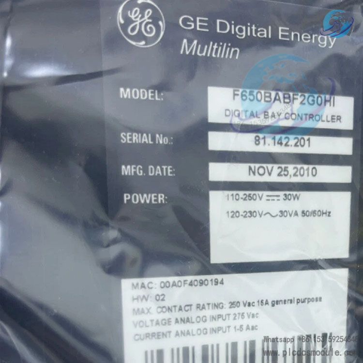
Model Code Breakdown: F650BABF2G0HI
Code segmentation rule: F650-B-A-B-F2-G0-HI
F650: Product series code, digital bay controller series for feeders based on Multilin 650 platformB: Display panel configuration. B = Basic monochrome backlit LCD panel with simple operation keys, without single-line graphic displayA: 1st rear communication board. A = Dual redundant RS485 serial communication portsB: 2nd rear communication board. B = 10/100Base-TX 100 Mbps Ethernet communication moduleF2: Slot F I/O card. Digit 2 = Standard I/O board with 16 galvanically isolated digital inputs and 8 relay outputsG0: Slot G expansion I/O card. Digit 0 = No expansion I/O module, no additional external digital input/output pointsHI: Auxiliary power supply specification. HI = Wide-range universal power supply, 110~250 VDC / 120~230 VAC
Core Advantages
- Integrated all-in-one design cuts auxiliary cabinet material costs. A single unit integrates five functions: protection, measurement, control, fault waveform recording and communication. It eliminates procurement expenses for separate measuring & control devices, fault recorders and time synchronizers.
- Pluggable modular hardware drastically reduces maintenance replacement time. The CPU board, communication boards, I/O boards and power supply are separate independent modules. If one module fails, full-unit disassembly is unnecessary, and on-site replacement takes less than 15 minutes to shorten power outage maintenance windows.
- Fully open standardized communication compatible with smart substations. It natively supports multiple protocols including IEC61850 Ed.2, DNP3, Modbus TCP/RTU and IEC60870-5-104, with PRP/HSR network redundancy capability, and works with mainstream integrated automation monitoring systems and remote terminal units (RTUs).
- High-precision fault tracing capability. Equipped with multi-mode time synchronization: IEEE 1588 PTP, IRIG-B and dual SNTP. It stores 479 SOE records, complete fault oscillography and load data logs, greatly improving efficiency in fault localization and post-fault analysis.
- IEC61131-3 compliant programmable logic with built-in virtual I/Os. Users can customize logics such as bus interlocking, automatic bus transfer, load shedding and arc flash interlock, eliminating complicated secondary wiring with external intermediate relays.
- Stable operation over wide temperature range. Standard units operate reliably from -25℃ to +70℃. Certified with CE, UL508 and SIL2 safety standards, it resists grid transient surges and cabinet electromagnetic interference, suitable for harsh industrial electromagnetic environments.
Applicable Industrial Scenarios
New Energy Power Stations
Feeder bay protection for PV booster stations and wind turbine box transformers; anti-islanding control at distributed grid connection points
Rail Transit
Integrated protection, measurement and control for incoming feeders, bus couplers and outgoing feeders of 35kV/10kV step-down substations in metro and intercity railway systems
Large Industrial & Mining Enterprises
Self-owned substations for smelting, chemical and coal mining industries; protection and control for high-voltage motors and factory transformers
Municipal Power Industry
Automation retrofitting projects for urban switching stations, ring main units and residential power distribution rooms
Data Centers
Incoming feeder protection and automatic bus transfer logic control for high-voltage power distribution rooms of IDCs
Commercial Complexes
10kV distribution bay monitoring for large shopping malls and office buildings
Water Conservancy & Hydropower
Auxiliary power feeder and busbar backup protection for small and medium-sized hydropower stations
FAQ
Q: Can model F650BABF2G0HI be used for main transformer protection of 110kV transformers?A: This model is positioned as a feeder bay controller and can only be applied as transformer backup protection. GE T650 series dedicated transformer protection relays are required for primary protection of 110kV main transformers.
Q: Is the HI power supply variant compatible with 220V commercial AC power supply?A: The HI-spec auxiliary power supply supports 120–230 VAC mains power as well as 110–250 VDC DC operating power. No extra power conversion modules are needed for standard power supply in distribution rooms.
Q: What alarm will be triggered if the CT secondary circuit of the device is open-circuited? How to troubleshoot it?A: Once the hardware detects CT wire breakage, a negative sequence abnormal alarm will pop up immediately, and partial protection functions will be blocked. Cut off the power supply at once to check the tightness of secondary terminals; never plug or unplug CT circuits under live voltage.
Q: How to troubleshoot frequent disconnections of IEC61850 communication?A: Check items in sequence: network cables, PRP redundancy configuration on switches, IP network segment of the relay, VLAN division of the monitoring background, and verify consistency between the internal communication protocol version in EnerVista and the monitoring system.
Q: Is power cut required for online firmware upgrade?A: A full firmware upgrade must be carried out with power disconnected. Only minor patch versions support online hot update. Be sure to back up all setting values, logic programs and oscillography files before any upgrade.
Q: Why does the relay trip on protection operation without any fault oscillography data?A: This is most likely caused by excessively high trigger threshold parameters for oscillography or full storage partitions. Adjust the fault recording startup threshold via software and export & clear historical oscillography files regularly.
Q: Can external remote I/O modules be connected to F650BABF2G0HI to expand I/O points?A: The unit only comes with standard 24 I/O points on Slot F and no expansion card on Slot G. However, a CAN bus interface is reserved on the backplane to connect external CIO remote I/O modules for additional digital points.