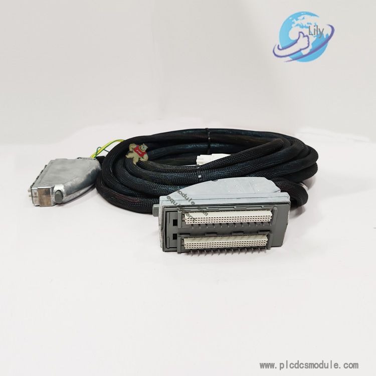
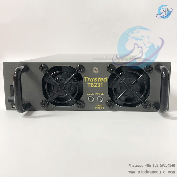
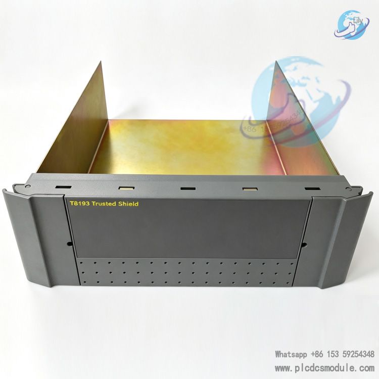
ICS TRIPLEX T3120 Processor Module
1. Product Overview
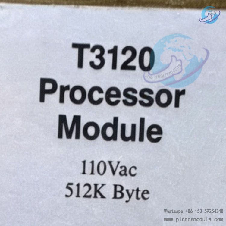
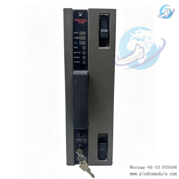
ICS TRIPLEX T3120 is a 512K large‑capacity triple redundant processor module for Regent PD6000 safety control system. It is compatible with T3100 rack with 85~132VAC power supply and serves as the TÜV certified SIL5 safety core unit. Three pieces of T3120 modules are required to run synchronously in one complete system. It adopts 2‑out‑of‑3 hardware voting architecture to realize 3‑2‑0 fault‑tolerant operation. T3120 integrates independent main processor, I/O processor and isolated power circuit. Single‑module fault will not interrupt control logic. Equipped with lithium battery backup memory and supporting hot‑swap without program re‑downloading. One T3120 processor group can expand up to 16 I/O racks, supporting large‑scale process safety control with more than 300 I/O points. It is the core computing hardware for SIS safety instrumented systems in petroleum, chemical and power industries.
2. Core Technical Specifications
Electrical Specifications
- Power Compatibility: Matches T3100 rack, input voltage 85~132VAC, frequency 47~63Hz, max overall power consumption 100VA, single‑module heat dissipation 46W (156BTU/h)
- Fuse Specification: Rack‑mounted 3AG type 2A/250V time‑delay fuse
- Fault Contact: Category‑2 circuit, max load 1A, max switching voltage 30VAC/42.5VDC, resistive switching capacity 30VA
- Power Hold‑up: Minimum 10ms power‑fail hold‑up time to guarantee uninterrupted scan cycle
Memory & Operation
- Memory: 512K battery‑backed CMOS RAM, system firmware occupies 64K (27K system kernel + 37K runtime buffer)
- Program Scan Cycle: Maximum allowable 400ms. RUN LED stays solid on scan overtime; normal idle blink rate 2Hz, cold‑start loading slow blink 0.5Hz
- Memory Backup: Lithium‑sulfur‑dioxide battery, 10‑year shelf life, maintains memory data for 6 months after power loss
Bus & Expansion
- Safetybus Safety Bus: Maximum single‑link cable length 45 meters (150 feet)
- I/O Expansion: One T3120 processor group supports up to 16 I/O racks for large‑scale interlock control
- Communication Response: Fixed 1ms read‑write cycle for communication modules, message verification executed at end of scan cycle
Environmental & Mechanical Parameters
- Operating Temperature: 0℃~60℃; Storage Temperature: -40℃~85℃
- Humidity: 0~95% RH non‑condensing
- Vibration Resistance: 10~55Hz ±0.15mm amplitude; Shock Resistance: 15g half‑sine wave, 11ms duration
- EMC Compliance: IEC801 ESD Level‑3 6kV, Radiated Field Level‑3 10V/M, EFT Level‑4 2kV, Surge Level‑3 2kV
Physical Dimension: Height 320mm, Width 32mm, Depth 257mm; Unit Weight: 3.4kg (7.5 lbs)
3. Key Functional Advantages
- Triple Modular Redundancy TMR 3‑2‑0 Fault‑Tolerant Architecture: Three T3120 modules run fully independent lock‑step synchronization. All computations, I/O access and communication data pass through 2‑out‑of‑3 hardware voting. Upon transient, intermittent or permanent fault of one T3120, the faulty channel is isolated automatically. Two healthy modules maintain full control output without single‑point shutdown risk.
- Hot‑Swap Maintenance Without Shutdown: T3120 supports online hot replacement. Remove faulty module and insert new T3120, trigger voting reset via front‑panel button. Background diagnostic synchronizes program, firmware and fault logs automatically. No program re‑download required, production keeps running.
- Timestamped Fault History Logging: On‑board timestamp fault memory stores all processor, I/O, communication and power failures. Fault sequence logs can be retrieved via WINTERPRET software to distinguish transient interference vs permanent hardware damage and shorten troubleshooting time.
- Dual‑Processor Parallel Architecture: Each T3120 integrates 68000 main processor + Z80 I/O processor. Shared RAM serves as data mailbox for task partition. Main processor executes control algorithm, diagnostics and communication scheduling. Z80 I/O processor independently reads field signals. Dual‑core separation reduces load and improves scan stability.
- Multi‑Level Hardware Diagnostics: Periodic automatic EPROM checksum verification, RAM read‑write test and voting circuit self‑test. After new module insertion, background diagnostic completes synchronization calibration and continuously monitors Safetybus link status.
- Program Tamper‑Lock Mechanism: Front‑panel memory lock key switch. When at least two of three T3120 modules are switched to lock position, control programs are locked, forcing output function of host software is disabled to prevent accidental modification of interlock logic.
Power‑Fail Data Protection: On‑board independent lithium battery preserves user application program and runtime buffer after full rack power loss. Program retention up to 6 months without re‑download upon power restore.
4. Product Basic Features
- Multi‑Channel Front‑Panel Status LEDs: Seven groups of bi‑color LED indicators: PROC, COMM, I/O, RUN, BATT, MEMLK, POWER. Red LED for fault status, green LED for normal operation. Field personnel can quickly judge module health status.
- Voting Reset Push‑Button: Trigger voting reset by pressing reset buttons simultaneously on two healthy T3120 modules. Fault alarms are cleared and new‑module program synchronization is completed. I/O access and control computation keep running during reset; only fault log reporting is temporarily suspended.
- Structured Function‑Block Programming Support: Works with WINTERPRET configuration software, supports standard structured function‑block programming and multi‑task parallel execution for complex ESD emergency shutdown, FGS fire‑gas interlock and unit protection logics.
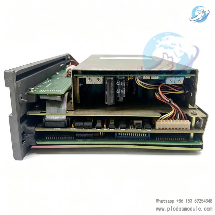
- Isolated Individual Power Design: Each T3120 has dedicated power conversion circuit converting rack AC input to board‑level logic voltage. Power failure of single module only affects its own channel; other two processors remain unaffected.
- Redundant Fault Alarm Contact: Dedicated fault relay contact activates upon permanent hardware failure, driving external alarm beacons or DCS host for remote fault notification.
5. Application Fields
- Oil & Gas Upstream & Refining: Offshore platforms, refineries, gas processing plants ESD emergency shutdown and FGS fire‑gas interlock systems. TMR architecture mitigates leakage and explosion hazards.
- Thermal & Gas‑Fired Power Plants: Safety protection for steam turbines, boilers and gas turbines, interlock shutdown logic for high‑low voltage equipment to ensure controlled unit trip under fault conditions.
- Fine Chemical & Coal‑Chemical Plants: SIS safety instrumented systems for reactors, distillation columns and pressurized process units, over‑temperature / over‑pressure trip control complying with high‑risk process safety requirements.
- Water Treatment & New‑Energy Energy Storage: Fire interlock for large‑scale battery energy storage cabins, safety trip for chemical wastewater treatment for continuous‑run safety‑critical scenarios.
Pharmaceutical & Pressure‑Vessel Equipment: Safety interlock for high‑pressure sterilization and closed reaction equipment, meets SIL5 process safety control standards.
6. T3120 Working Principle
Three T3120 processor modules are deployed in one control system, executing full scan cycles in lock‑step synchronization. Operation is divided into three logic layers:
Signal Acquisition Layer
Z80 I/O processor inside each T3120 reads field I/O module signals independently via dedicated Safetybus. Raw data is stored into local RAM and forwarded to shared RAM. Three‑channel data streams are delivered to all on‑board voters for 2‑out‑of‑3 hardware filtering to reject abnormal interference signals.
Logic Computation Layer
68000 main processor reads voted input data from shared RAM and executes user function‑block control programs. Calculated output results are written back to shared RAM. Three T3120 modules perform independent synchronous computation and cross‑vote output results.
Output Execution & Diagnostic Layer
I/O processor reads voted output data from shared RAM and sends commands via Safetybus to field output modules for actuator drive. Background self‑test continuously monitors processor, bus, battery and memory status. Fault events with timestamps are saved to local fault history memory.
When one T3120 fails, voting circuit masks its channel data. Remaining two modules maintain full computation and I/O links. After inserting replacement T3120, voting reset triggers system‑wide diagnostic, synchronizing existing programs and fault records to new module’s 512K RAM. Full triple‑redundant mode resumes upon synchronization completion.
7. Compatible Part Numbers
1. Controller Rack (Mandatory)
- T3100 Controller Rack (110VAC dedicated for T3120 / T3110 processors)
2. I/O Modules
- T3480 4‑20mA Safety Analog Output Module
- T3491 Remote Multiplexer I/O Communication Module
- MIU3201 Remote Multiplexer Interface Unit
- MIU3202 64‑Point Remote Digital Input Unit
- MIU3204 64‑Point Remote Digital Output Unit
3. Spare Parts & Consumables
- T3120 Lithium‑Sulfur‑Dioxide Backup Battery
- T3120 U42/U43/U19 System EPROM Firmware Chips
- ESD wrist strap & anti‑static mat for module installation
4. Host Communication Accessories
- WINTERPRET Configuration Software (for program download & fault monitoring)
8. Frequently Asked Questions
Q1: How many T3120 modules are required for one complete Regent PD6000 system?
A1: Three T3120 modules must be deployed synchronously to realize 2‑out‑of‑3 voting. Single or dual‑module configuration cannot satisfy fault‑tolerance requirements and will trigger redundancy loss alarm.
Q2: Can T3120 and T3110 run mixed in one control system?
A2: Not allowed. T3120 has 512K memory while T3110 only has 128K. Memory mismatch will cause program synchronization failure. All processors within one system shall be identical model.
Q3: Shall system be shut down or powered off for T3120 replacement?
A3: No shutdown or power‑off required. T3120 supports hot‑swap. Confirm other two modules show no PROC fault red LED and RUN indicator blinks normally. Remove faulty unit, insert new T3120 and perform front‑panel voting reset.
Q4: What does extinguished BATT indicator mean on T3120 front panel?
A4: Backup lithium battery capacity is low and shall be replaced soon. If power‑off duration exceeds 6 months, stored control programs will be lost and program re‑download will be necessary after power‑on.
Q5: What is maximum I/O point capacity of T3120?
A5: One triple‑T3120 group supports up to 16 I/O racks. T3120 is preferred for applications over 300 I/O points; T3110 (128K) applies for smaller systems within 300 points.
Q6: How many reset buttons need to be pressed for voting reset operation?
A6: Press RESET buttons simultaneously on two healthy running T3120 modules. Pressing only one reset button cannot complete synchronization for newly inserted module.
Q7: How to confirm rack model when ordering T3120?
A7: T3120 is exclusively for T3100 (110VAC) rack. Select T3121 for 220VAC rack T3101 and T3122 for 24VDC rack T3102. Wrong rack model results in no POWER LED upon power‑up.
Q8: Can EPROM chips of T3120 be replaced individually?
A8: U42, U43 (main processor board) and U19 (I/O processor board) EPROM chips can be replaced separately. Complete Regent PD6000 system must be powered‑down before replacement. Different firmware‑version EPROMs cannot be mixed.
9. Related Model List
- T3110 128K 110VAC Triple Redundant Processor Module
- T3111 128K 220VAC Processor Module
- T3112 128K 24VDC Safety Processor Module
- T3120 512K 110VAC SIL5 Safety Processor Module
- T3121 512K 220VAC Processor Module
- T3122 512K 24VDC SIL5 Processor Module
- T3100 110VAC Controller Rack
- T3101 220VAC Controller Rack
- T3102 24VDC Controller Rack
- T3480 4‑20mA Safety Analog Output Module
- T3491 Remote Multiplexer I/O Communication Module
- MIU3201 Multiplexer Interface Unit
- MIU3202 64‑Point Remote Digital Input Unit
- MIU3204 64‑Point Remote Digital Output Unit
- T8312 Trusted Series Expansion Interface Adapter Unit