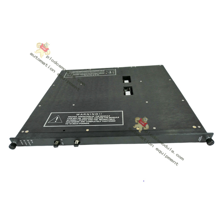
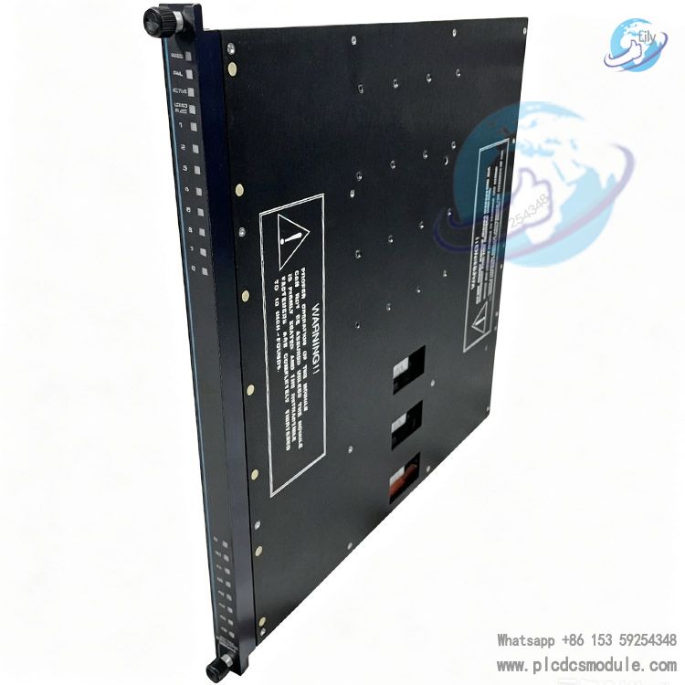
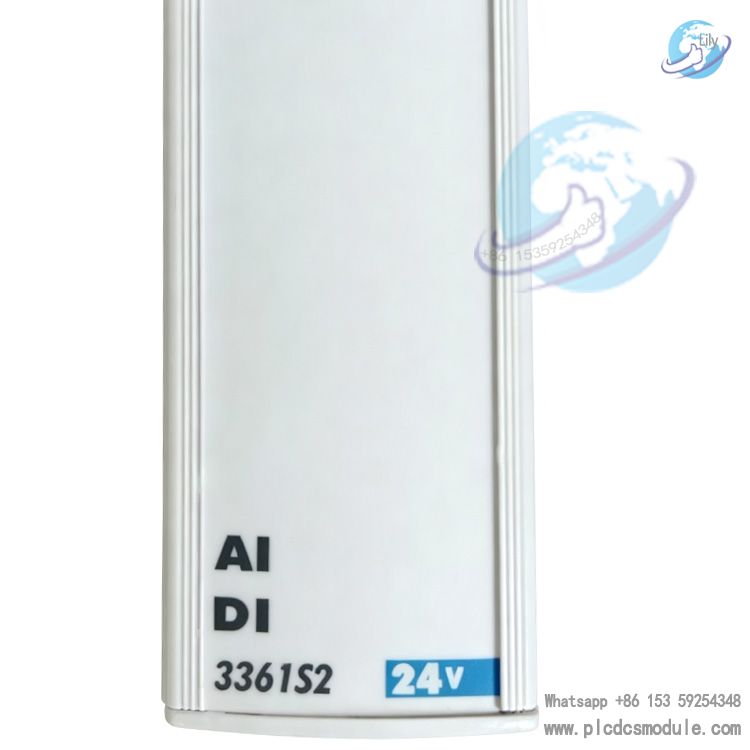
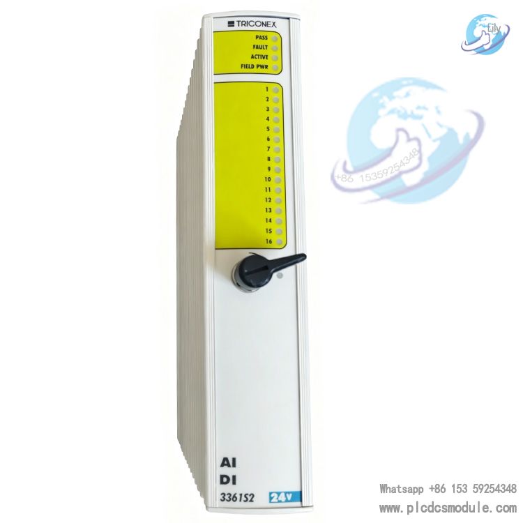
TRICONEX 3361S2 AI/DI Mixed Input Module
Product Overview
TRICONEX 3361S2 is a 32‑point mixed AI/DI input module for the Tricon v2 system. Channels can be flexibly configured for either analog input or digital input. Adopting TMR Triple‑Modular Redundancy architecture for SIS safety instrumented systems, it can simultaneously acquire 4‑20mA analog field signals and 24VDC discrete switch signals.
The 3361S2 integrates analog acquisition loops and digital input circuits within one single hardware unit, reducing chassis slot occupation and lowering project hardware procurement costs.
This module integrates isolation filters, ADC, DAC, ASIC chips and isolated bus transceivers. Three independent signal links output data to the triple‑redundant I/O Bus A/B/C. Single‑channel faults will not cause full‑module failure. It is widely deployed in high‑safety industrial applications such as ESD emergency shutdown and F&G fire‑and‑gas protection systems.

Technical Specifications
| General Parameters for All Channels | |
| Total Channels | 32 points, common‑ground design |
| Functional‑to‑Protective Ground Isolation Voltage | Min. 500 VDC |
| Logic Isolation Voltage Between Functional Grounds | Min. 800 VDC |
| AI Analog Input Channel Parameters | |
| Nominal Input Current | 4‑20mA DC |
| Effective Operating Current Range | 2‑22mA DC |
| Maximum Field Withstand Voltage | 33 VDC |
| Reverse Maximum Withstand Voltage | ‑0.6 VDC |
| Maximum Input Current | 50 mA DC |
| Input Bandwidth (3dB) | 16 Hz |
| Source Impedance | 180 Ω |
| Input Impedance with Baseplate | 250 Ω |
| I‑V Conversion Resistance | 100 Ω ±0.01% |
| Sampling Resolution | 12‑bit |
| Full‑Scale Absolute Error | 0.15% (20mA range) |
| Diagnostic Capability | FVD Force‑to‑Value diagnostics |
| Scan Period for All 32 Channels | <1 ms |
| DI Digital Input Channel Parameters | |
| Nominal Input Voltage | 0‑24 VDC |
| Effective Operating Voltage Range | 15‑30 VDC |
| Maximum Input Voltage | 33 VDC |
| Reverse Maximum Input Voltage | ‑0.6 VDC |
| Input Delay | <10ms (both ON/OFF transitions) |
| Input Impedance (without baseplate) | >100 kΩ |
| Input Impedance (with baseplate) | Approx. 3 kΩ |
| Per‑channel Power Consumption | 0.2W@24VDC;0.5W@33VDC |
| Input Threshold Zones | 0‑5VDC = Disconnect, 6‑14VDC = Transition, 15‑30VDC = ON |
| Diagnostics | FVD Force‑to‑Value diagnostics, single test duration <2ms |
Core Advantages
- Single‑module mixed AI & DI signal acquisition. Hardware channels can be flexibly assigned to save cabinet slots and reduce requirements for baseplates and cable materials.
- Complete TMR triple‑redundant signal links with three independent ADC sampling circuits and isolated bus transceivers. Single‑point channel faults will not interrupt system operation to meet high‑availability safety‑system requirements.
- Built‑in channel‑level FVD Force‑to‑Value diagnostics capable of locating individual channel anomalies instead of only module‑level alarms, supporting fast on‑site loop troubleshooting.
- Full‑32‑point scan time below 1ms delivers fast signal response for rapid signal acquisition of interlock protection loops.
- High‑grade electrical isolation up to 800VDC between functional logic grounds, improving immunity against electromagnetic interference for complex electromagnetic environments in chemical and oil‑gas sites.
- Online hot‑spare maintenance supported. With matched baseplate, the 3361S2 module can be replaced without system shutdown and without interruption of field safety‑signal acquisition.
Product Features
1. 32‑point common‑ground channels. Each channel can be software‑configured for AI analog or DI digital mode. On‑board filter termination components are activated only under DI mode.
2. Every signal point features independent isolation‑filter circuitry. Field signals pass filtering before feeding three separate ADCs for analog‑to‑digital conversion; DAC provides excitation for FVD diagnostic loops.
3. ASIC chip performs signal processing; isolated bus transceivers transmit processed data to the triple‑redundant A/B/C I/O buses respectively.
4. Mechanical anti‑mis‑insertion latch prevents improper installation of 3361S2 onto incompatible baseplates and avoids hardware configuration errors.
5. Channel‑level fault detection. Fault status can be uploaded to host monitoring software for maintenance personnel to identify exact faulty channel locations.
6. Clear voltage threshold zones for DI channels define disconnect, transition and ON states to prevent false switching caused by on‑site voltage jitter.
Application Fields
TRICONEX 3361S2 pairs with Tricon v2 safety instrumented systems, widely used for safety‑interlock scenarios requiring simultaneous acquisition of analog process signals and discrete status signals.
Oil & Gas: offshore platforms, long‑distance pipeline ESD emergency‑shutdown systems; acquiring 4‑20mA pressure transmitter signals, valve limit switches and flame‑detector discrete signals.
Refining & Chemical: plant‑wide SIS safety interlocks; analog acquisition of reactor and tank pressure / level signals plus discrete inputs for emergency‑stop push‑buttons and safety‑gate switches.
Power Industry: boiler BMS burner‑management and turbine‑protection systems; collection of analog process parameters plus feedback from circuit breakers, pumps and valves.
Coal‑to‑Chemicals: F&G fire‑and‑gas systems for mixed acquisition of gas‑detector analog signals and heat‑detector discrete signals.
Pharmaceutical & Fine‑Chemical: high‑hazard‑process safety instrumented systems for mixed acquisition of analog process parameters and safety discrete points.
Product Comparison
| Model | Channel Type | Channel Count | Key Differences |
| 3361S2 | AI/DI Mixed Input | 32 points | Freely switch AI / DI; ideal for mixed‑signal projects, saves cabinet space |
| 3351 | Pure AI Analog Input | 32 points | 4‑20mA analog‑only input, no DI function; for full‑analog point applications |
| 3301 | Pure DI Digital Input | 32 points | 24VDC discrete‑only processing, no analog acquisition; for heavy discrete‑signal scenarios |
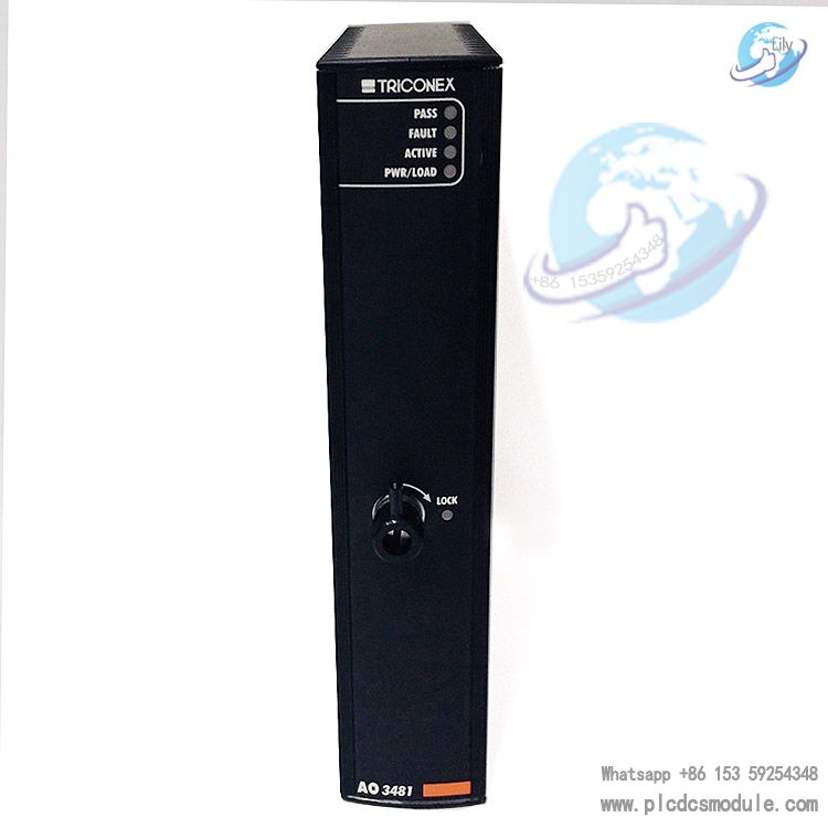
| 3481 | AO Analog Output | 32 points | 4‑20mA output for field control‑valve driving; output‑only, no input acquisition |
Matching Accessories
- Module Baseplate: 2361 AI/DI baseplate kit. Mandatory for 3361S2 for field‑wiring transition and impedance matching.
- TriPak Assembly Kit: 5361 (kit contains 3361S2 module + 2361 baseplate)
- External Terminal Panel: 9764510 external terminal block for signal transition between field cables and 2361 baseplate
- Controller: 3101 main processor module, core CPU for Tricon v2 platform; 3361S2 I/O modules connect to its backplane bus
- Communication Module: 3201 communication module for host‑system interaction and reading field data acquired by 3361S2
Recommended Models from Same Series
- 3301 Digital Input Module
- 3351 Analog Input Module
- 3401 Digital Output Module
- 3451 Solid‑State Relay Output Module
- 3481 Analog Output Module
- 3482 High‑Current Analog Output Module
- 3101 Main Processor Module
- 3201 Communication Module
- 3381 Pulse Input Module
- 3506X Supervised Digital Input Module
- 3626X Supervised Digital Output Module
- 3722X Analog Input Module
- 3809X Analog Output Module
- 3902X Universal I/O Module
- 2301 Digital Input Baseplate Kit
Notes
- 3361S2 is exclusively compatible with the Tricon v2 hardware platform. It cannot work with legacy first‑generation Tricon hardware or newer Tricon CX platform. Confirm controller hardware revision before selection.
- AI‑mode input loops require the 2361 baseplate to achieve standard 250Ω input impedance. Analog sampling accuracy will drift without the matched baseplate.
- Under DI mode, 6‑14VDC is the voltage transition zone. Field wiring design shall avoid sustained input within this range to prevent frequent discrete‑signal toggling.
- FVD Force‑to‑Value diagnostics temporarily alter channel levels. Evaluate diagnostic test cycles during logic configuration to avoid interlock‑logic disturbance.
- Never exceed maximum field withstand voltage. Input voltages higher than 33VDC will permanently damage 3361S2 channel hardware.
- Hot‑spare module replacement shall follow official Tricon maintenance procedures. Verify firmware version consistency between spare unit and live system; version mismatch triggers communication anomalies.
- Strictly follow manual instructions for functional‑ground and protective‑ground wiring. Isolation performance depends on proper grounding; poor grounding degrades EMI immunity.
FAQ
Q: Can partial channels of 3361S2 run as AI analog and others as DI digital?
A: Yes. Each of the 32 channels can be independently software‑configured for AI or DI without hardware rewiring. Extra filter termination components are only enabled under DI mode.
Q: Is it mandatory to order the 2361 baseplate together with 3361S2?
A: Yes. 3361S2 cannot connect field cables directly. The 2361 baseplate provides terminal access and impedance matching. Alternatively procure the complete 5361 Tripak kit containing both module and baseplate.
Q: What is FVD diagnostic for 3361S2 and can it be disabled?
A: FVD stands for Force‑to‑Value diagnostics. The module injects internal test signals to verify loop integrity. It can be enabled or disabled via configuration software. Single DI‑channel test takes less than 2ms.
Q: What are the analog‑input accuracy specifications for 3361S2?
A: Analog resolution is 12‑bit; full‑scale (20mA) absolute error 0.15%. Effective operating current range is 2‑22mA DC for nominal 4‑20mA transmitter signal acquisition.
Q: Does 3361S2 support online non‑stop replacement?
A: Hot‑spare architecture is supported. Under hot‑standby system configuration, faulty 3361S2 can be swapped online without interrupting acquisition of remaining channels. Confirm firmware version compatibility before replacement.
Q: Can 3361S2 be used within Tricon CX systems?
A: No. 3361S2 belongs to Tricon v2 platform I/O hardware; its hardware bus protocol is incompatible with CX‑series controllers. For CX platform select CX‑specific I/O such as 3506X and 3722X.
Q: What input‑voltage level defines DI ON status?
A: Valid DI ON range is 15‑30VDC; 0‑5VDC defines OFF; 6‑14VDC is transition zone with unstable signal status. Avoid operating within this voltage range in engineering practice.
Q: What is full‑scan time for all 32 channels on one 3361S2?
A: Complete scan across all 32 channels is less than 1ms, delivering fast signal acquisition for safety interlock applications.