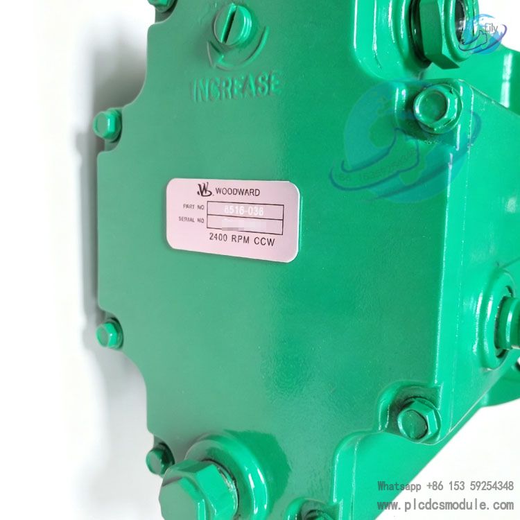
Woodward 8516‑038 TG‑13 Hydraulic Governor
Product Introduction
Woodward 8516‑038 TG‑13 is a mechanical‑hydraulic droop governor within the TG series. It is mainly designed for small‑size steam turbine units and applied in control scenarios that do not require isochronous synchronous operation. The 8516‑038 TG‑13 picks up turbine speed signals via the drive shaft, compares them with internal speed setpoint, and drives the turbine regulating valve through the output shaft to adjust steam intake flow for speed control.
The 8516‑038 TG‑13 features an integrated oil sump. Its oil pump assembly is driven by the drive shaft, so no external hydraulic oil source is required, simplifying on‑site piping layout. This governor is widely deployed in small steam turbine systems complying with API611 standard, commonly used in petrochemical, auxiliary power‑generation equipment, pump sets and compressor drive applications. It represents a proven mechanical‑hydraulic governing solution for industrial turbine control.
Technical Specifications
| Speed Setting Range | 1200‑2400 rpm |
| Rated Droop | 2010 rpm, 2° set point |
| Drive Shaft Rotation | CCW (counter‑clockwise) viewed from top |
| Output Shaft Torque | 16 N・m, approx. 12 ft‑lb |
| Maximum Travel of Terminal Shaft | 40°, recommended to use approx. 2/3 travel range from no‑load to full‑load |
| Internal Operating Oil Pressure | 1034 kPa, approx. 150 psi |
| Drive Shaft Dimension | 1/2‑inch diameter, No.5 Woodruff keyway |
| Steady‑State Speed Band | ±0.75% of rated speed, compliant with NEMA‑A standard |
| Ambient Operating Temperature | ‑29℃ ~ +93℃ |
| Housing Material | Die‑cast aluminum alloy with weather‑resistant construction |
Core Advantages
- Adopts integrated self‑oil‑supply structure, reducing failure points brought by external hydraulic oil source and piping
- Mechanical‑hydraulic closed‑loop structure is immune to electromagnetic interference, suitable for factory environments with heavy electrical noise
- Governor droop can be internally adjusted for tuning according to varying turbine load characteristics
- Rugged housing construction withstands vibration and temperature fluctuations commonly seen in chemical and energy‑industry sites
- Mature disassembly and maintenance procedures with abundant industry servicing experience, keeping long‑term maintenance costs under control
- Power‑supply independent design; basic governing actions remain available upon power loss to improve unit safety redundancy
Product Features
- Equipped with screw‑type speed‑adjustment mechanism; speed setpoint can be modified on the top cover of the unit
- Output shaft can extend out from both housing sides, facilitating linkage installation in different orientations on‑site
- Built‑in accumulator‑relief valve assembly stabilizes internal oil pressure under transient conditions and mitigates speed fluctuation
- Oil sump fitted with sight glass for intuitive visual oil‑level inspection by maintenance personnel
- Qualified for ATEX hazardous‑area deployment to satisfy installation requirements in explosion‑proof plant zones
TG‑13 unit integrates speed sensing, hydraulic power and output actuation functions within compact footprint

Application Fields
- Petrochemical steam turbine control for process pump, compressor and expander speed management
- Small‑size steam turbine control for thermal power and self‑owned power plants for fans and auxiliary units under non‑isochronous conditions
- Turbine unit control for oil‑gas production sites for gas compression equipment speed regulation
- Industrial plant induced‑draft and forced‑draft equipment control for turbine‑driven fan governing
- API611‑compliant small steam turbine installations for process loops without isochronous synchronization requirements
Same‑Brand Product Comparison
Compared with TG‑17 series governors, the TG‑17 delivers higher output torque around 23.7 N・m and internal oil pressure up to 1379 kPa. It fits turbines with larger load torque while featuring bigger overall dimension and higher procurement cost.
8516‑038 TG‑13 uses screw‑type speed adjustment, whereas TG13‑L adopts lever‑type speed setting. Both share similar torque parameters but differ in speed‑adjustment operation. TG‑13E is an electro‑hydraulic actuator requiring electric signals and matching electronic controllers, while 8516‑038 TG‑13 is purely mechanical‑hydraulic without any electrical signal interfaces. TG611‑13 is a derivative of TG‑13 with additional overspeed‑test hardware, preferred for units demanding frequent overspeed tests.
Related Matching Products
- 9904‑814, TG‑13 alternative reference model without overspeed‑test device
- 8516‑175, upgraded TG‑13 replacement model integrated with overspeed‑test device OTSD
- OTSD 04042, document reference number for TG‑13 / TG‑17 service manual
- Compatible with Woodward 2301 electronic controller for hybrid electronic‑mechanical‑hydraulic governing retrofits
- Governing linkage assembly: standard spline connection kit 04042‑SP‑01
- TG‑series dedicated anti‑wear hydraulic oil for internal oil‑sump lubrication circuit
FAQ
Q: Does 8516‑038 TG‑13 support isochronous synchronous operation mode?
A: The 8516‑038 TG‑13 is a droop governor and does not support hardware‑based isochronous synchronous operation. For isochronous control, adopt a combined solution with electronic controller and electro‑hydraulic actuator.
Q: What parts shall be prioritized for troubleshooting when 8516‑038 TG‑13 suffers speed drift or heavy fluctuation?
A: Prioritize inspection of internal oil level and oil cleanliness, drive‑shaft transmission clearance, droop setting parameters, and check whether output linkage is stuck or has excessive backlash. Oil degradation is a common on‑site failure trigger.
Q: Can 8516‑038 TG‑13 be directly installed as a replacement for TG‑17?
A: Mounting holes may be compatible, yet output torque capacity differs. Direct substitution with 8516‑038 TG‑13 may result in insufficient actuation force for turbines with high load torque. Direct swap‑out is not recommended; unit torque parameters must be calculated beforehand.
Q: Can drive‑shaft rotation direction of 8516‑038 TG‑13 be modified on‑site?
A: Model 8516‑038 is fixed to CCW rotation; pump rotation direction cannot be altered on‑site. Select corresponding CW part number if unit input rotation direction is different.
Q: What key parameters need confirmation when purchasing 8516‑038 TG‑13?
A: Confirm unit rated speed range, drive‑shaft rotation direction, output torque requirement, ATEX explosion‑proof qualification necessity, and whether OTSD overspeed‑test function is required.
Q: What oil shall be filled into 8516‑038 TG‑13 internal oil sump? How frequently shall oil level be checked?
A: Turbine anti‑wear hydraulic oil is recommended; follow service documentation for exact oil specification. Oil‑level inspection can follow regular turbine maintenance cycles; shorten inspection intervals for harsh operating environments.
Q: Is full 40° output‑shaft travel supposed to be consumed?
A: Long‑term full‑stroke 40° operation is not advised. Utilize approximately 2/3 of maximum travel between no‑load and full‑load. Reserved margin helps extend service life of hydraulic components.
Recommended Same‑Brand Models
- 8516‑038 TG‑13 Hydraulic Governor
- 9904‑814 TG‑13 Governor
- 8516‑175 TG‑13 Governor with OTSD
- 8516‑041 TG13L Lever‑Operated Governor
- 8516‑039 TG‑13 4000RPM Governor
- 8516‑044 TG‑17 2400RPM Governor
- 8516‑045 TG‑17 4000RPM Governor
- 8516‑046 TG‑17 6000RPM Governor
- 8516‑191 TG611‑17 Governor
- TG‑13E Electro‑Hydraulic Actuator
- TG‑17E Electro‑Hydraulic Actuator
- 9904‑800 TG‑17 ATEX Governor
- 9904‑817 TG13L ATEX Governor
- A8516‑038 TG‑13 CW Governor
- C8516‑043 TG13L 6000RPM Governor
Notes
- During installation of 8516‑038 TG‑13, keep drive‑shaft alignment within allowable tolerances to avoid extra radial load applied to internal governor bearings.
- Droop‑parameter tuning must be performed against actual turbine load. Excessively small droop setting may trigger unit speed oscillation.
- Mixing different hydraulic‑oil types is prohibited. Drain and replace oil promptly upon water ingress or emulsification to prevent spool sticking.
- Maintain reasonable clearance for output linkage; never force‑pull output shaft, or internal hydraulic assemblies may get damaged.
- Store in dry and ventilated surroundings. Perform periodic visual oil‑level checks for long‑term static storage.
- For retrofit‑replacement projects, verify speed range, rotation direction and explosion‑proof requirements. Do not rely merely on TG‑13 series name; part number 8516‑038 covers multiple configuration variants.
Product Tags
Woodward 8516‑038,TG‑13 hydraulic governor,mechanical‑hydraulic governor,steam turbine governor,TG series governor,8516‑038 governor,Woodward TG‑13