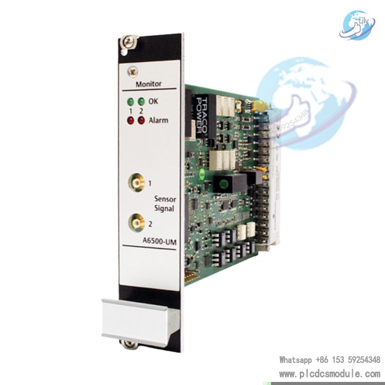
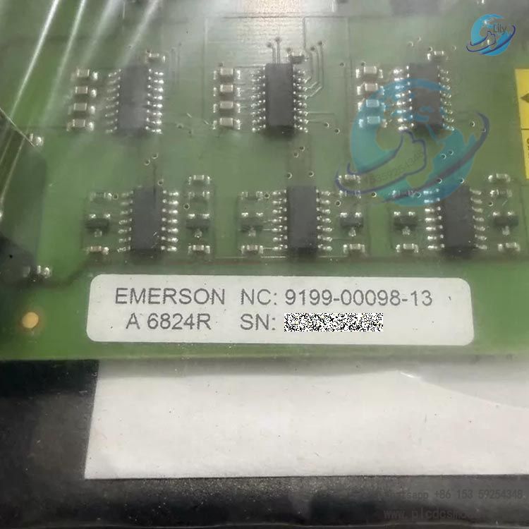
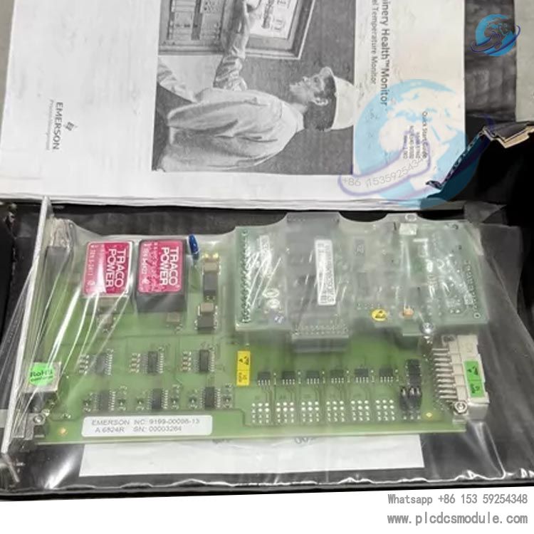
EMERSON A6824R (9199‑00098‑13) AMS6500 ModBus Communication Module
Part Number: A6824R, Item Code: 9199‑00098‑13 The Emerson A6824R belongs to the AMS6500 (CSI6500) Machinery Health Monitoring System. It is a ModBus rack interface communication module designed for the IMR6500 series 19-inch rack. Redundancy mode is supported, and the module complies with API‑670 rotating machinery protection standards.

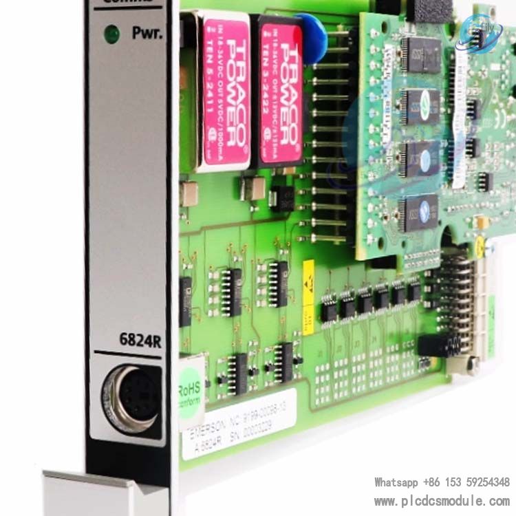
1. Product Overview
The A6824R serves as the core communication gateway board for the AMS6500 (CSI6500) protection rack. It collects machinery status data from all monitoring modules inside the rack and exports data externally via Modbus‑TCP/IP Ethernet and Modbus‑RTU serial ports. Dual communication links can be activated simultaneously to implement communication redundancy.
It transmits unit vibration, speed, gap, alarm and other data to DeltaV, Ovation DCS/PLC/SCADA systems, and integrates with the PlantWeb plant intelligent architecture and AMS Suite predictive maintenance software to realize online condition monitoring and early fault diagnosis of rotating equipment.
This module also supplies power for the local rack graphic display, enabling on-site reading of instrument and unit parameters. It supports hot swap, password configuration and hardware self-diagnostics. It is widely deployed in protection systems for critical rotating machinery such as steam turbines, gas turbines, compressors and hydroelectric generators.
A6824R vs A6824 Core Comparison
| Model | Rack Compatibility | Width | Redundancy Function |
|---|---|---|---|
| A6824R | IMR6500 (AMS6500) | 4TE | Optional redundancy mode |
| A6824 | IMR6000 Series | 6TE | Non-redundant, standalone use |
2. Hardware & Physical Specifications
Board form factor: DIN41494 standard EURO card format, 3U (3HE) height, single slot installation for 19-inch IMR6500 rack. Maximum 14 modules can be installed within one single rack.
Dimensions
- Width: 19.98 mm (4TE, 0.79 inch)
- Height: 128.4 mm (3HE, 5.055 inch)
- Depth: 160 mm (6.300 inch)
- Weight: Approx. 320 g net weight; approx. 450 g gross weight with package
Interfaces
- RJ45 Ethernet (10Base‑T); factory default IP: 192.168.255.1, Subnet Mask: 255.255.255.0
- RS‑485 serial port for Modbus‑RTU; baud rate: 19.2k; serial settings: 8 data bits, Even parity, 1 stop bit
Electrical
- Max power consumption: 5W, powered by rack backplane 24VDC
- Front panel indicators: Pwr power LED, Comms communication status LED
3. Supported Readout Data Types
The module collects data from all internal monitoring cards and exposes Modbus holding registers for the following process variables: Rotational speed; fractional vibration (1/2X, 1X, 2X vibration amplitude and phase); shaft gap / eccentricity; channel OK status; alarm and danger trip status; phase angle; module and sensor identification information.
4. Environmental & Reliability Ratings
- Operating temperature: 0 ~ +65 ℃
- Storage temperature: -30 ~ +85 ℃
- Relative humidity: 5‑95%, non-condensing
- Vibration resistance (IEC 68‑2‑6): 10‑55Hz, 0.15 mm amplitude; 55‑150Hz acceleration 19.6 m/s²
- Shock resistance (IEC68‑2‑29): peak 98 m/s², 16 ms duration
- EMC compliance: EN50081‑1 / EN50082‑2; backplane isolation 1500V RMS
- Certifications: API‑670 machinery protection standard; hot swap support; password protected configuration; hardware self-test (power supply, board temperature, hardware fault diagnosis)
5. Key Features
- Dual protocol concurrent operation for communication redundancy: Modbus‑TCP Ethernet and Modbus‑RTU serial port can run at the same time to build redundant communication paths. Data upload continues if one communication link fails, delivering high reliability for critical machinery protection systems.
- Hot-swap capability: Cards can be inserted or removed while the rack remains powered, no system shutdown required and other monitoring channels remain unaffected.
- Local display driver: Powers and drives the rack-mounted local graphic display for on-site viewing of unit and sensor readings.
- AMS Suite / PlantWeb integration: Seamless connection with Emerson DeltaV and Ovation DCS. Maintenance personnel can perform predictive diagnostics using AMS Suite software based on data uploaded by this module to identify rotating machinery faults in advance.
- Self-monitoring protection: Continuously monitors module hardware, input power and board temperature. Fault conditions are reported to control systems via Modbus registers.
- Password protected configuration: Communication and alarm mapping parameters require password access to prevent unintended on-site modification.
6. Application Scenarios
- Thermal power: Steam turbines, boiler feed pump sets
- Oil & Gas / Chemical: Gas turbines, centrifugal compressors
- Hydropower: Hydroelectric generator units
- API‑670 compliant machinery protection systems (AMS6500/CSI6500) for large critical rotating equipment, providing vibration protection and status data transmission to DCS/PLC.
7. Ordering Information
- A6824R: ModBus rack interface module with redundancy mode for AMS6500 / IMR6500 19" rack; Part Number: 9199‑00098‑13
- A6824: Non-redundant version for IMR6000 series rack
AMS6500 Classic IMR6500 Rack Common Card Selection Table
All cards support hot swap and comply with API‑670 standard. The 19-inch IMR‑6500 rack accommodates up to 14 modules in a single chassis.
- A6824R, Part No. 9199‑00098‑13, 4TE width, single slot occupancy. Core communication gateway card exclusively for IMR6500 rack. Provides Modbus‑TCP and Modbus‑RTU data output, supports communication redundancy and supplies power to the local rack display. Both communication protocols can run concurrently.
- A6110, Part No. 9199‑00001. Dual-channel shaft relative vibration card, accepts eddy current probe inputs, widely used for radial shaft vibration protection on turbines and compressors. Provides -26.7V sensor power supply. Each channel has independent alarm relay output.
- A6120 Dual-channel thrust shaft displacement card. Receives eddy current sensor signals to monitor thrust shaft displacement and shaft eccentricity, mainly for turbine thrust pad wear protection. Supports configurable gap alarm thresholds.
- A6125 Dual-channel speed and keyphasor card. Dual-channel input for speed acquisition and keyphasor phase calculation, outputs 1X, 2X and other harmonic vibration data. Compatible with magnetoelectric and Hall-effect speed probes.
- A6140, Part No. 9199‑00058. Dual-channel bearing housing absolute vibration card. Captures bearing case vibration from piezoelectric or velocity vibration sensors. Front panel SMB buffered output port for external spectrum analyzers for fault diagnosis.
- A6620 4-channel process input card. Accepts 4‑20mA, ±1V, ±10V analog signals to collect pressure, unit load and other third-party process variables for system alarm logic.
- A6740‑10 16-channel programmable relay card, 10TE width, occupies 2 slots. Provides 16 SPDT relay contacts, used for alarm logic voting and hard trip output. Supports 2-out-of-3 voting protection logic and is dedicated to IMR6500 rack. Unit protection trip must use hard relay contacts from this card. Modbus communication signals shall NOT be used for tripping.
- A6800 Rack power supply module. Outputs 24VDC to supply power to the IMR6500 rack backplane. 1+1 redundant configuration is recommended for critical unit projects to improve power reliability.
Auxiliary Components
- A6910‑KIT: Full configuration kit including software CD, configuration cables and adapters. Configuration tool for AMS6500 system parameter setup.
- IMR6500 19-inch rack backplane: Internal rack bus communication, power and data exchange for all cards.
- Rack local display: Powered by A6824R for on-site cabinet viewing of measurement points and alarm status.
Selection Guidelines
- At least one A6824R is required per IMR6500 rack. For high communication reliability requirements, two A6824R modules can be deployed for 1+1 communication redundancy.
- Unit protection trip logic shall be implemented via A6740‑10 relay card voting. Modbus is only for data monitoring and must not be used in unit trip circuits.
- All measurement cards support hot swap. After card replacement, sensor gap and alarm setpoints must be re-verified.
Frequently Asked Questions
Q1: Can A6824R and A6824 be directly interchanged?
A: Direct interchange is not possible. A6824R (4TE) is designed for IMR6500 rack with communication redundancy. A6824 (6TE) is built for IMR6000 rack without redundancy. Backplane hardware, slot width, firmware and configuration software versions differ; mixing cards is not allowed.
Q2: Will hot-swapping A6824R cause loss of machinery protection interlock?
A: The module supports API‑670 compliant hot swap. Only Modbus communication is temporarily interrupted. Measurement cards and hard relay protection interlock remain fully operational and machinery protection continues. Communication automatically recovers after module reinstallation, rack power cycle is not required.
Q3: Can Modbus‑TCP and Modbus‑RTU on A6824R be enabled at the same time?
A: Yes, both protocols can run concurrently to establish redundant communication links. If one communication path fails, the other continues transmitting measurement data. Default serial parameters: 8 data bits, Even parity, 1 stop bit, baud rate 19200. Factory default Ethernet IP: 192.168.255.1, Subnet Mask: 255.255.255.0.
Q4: Can A6824R collect data from multiple IMR6500 racks?
A: A6824R only collects measurement points inside its local rack. For multi-rack systems, each IMR6500 rack needs its own A6824R, and the DCS master accesses each module by individual IP address. Only the older non-R A6824 supports multi-rack data collection.
Q5: DCS cannot read A6824R Modbus tags. What items should be checked first?
A:
- Check front panel LEDs: steady Pwr = normal power supply; flashing Comms indicates active message exchange.
- Verify DCS master IP address, serial baud rate and parity settings.
- Use A6910 software to confirm no hardware faults on measurement cards.
- Confirm measurement point register output is not disabled in configuration.
- Read module diagnostic registers to check for module power and temperature alarms.
Q6: What to do if A6824R configuration password is lost?
A: IP and Modbus mapping settings are password protected to prevent unintended field modification. If the password is forgotten, use A6910 configuration software to restore factory defaults. This operation erases all communication configurations and full system re-configuration and download will be required.
Q7: If A6824R is removed, does the TSI system protection remain active?
A: Protection functions remain fully operational. Only two functions are disabled:
- Local rack graphic display loses power and cannot show readings on site.
- External Modbus data output stops. Measurement, alarm and hard relay interlock on A6740‑10 are unaffected.
Q8: Can Modbus signals be sent to DCS for trip interlock under API‑670 protection requirements?
A: Modbus signals are NOT permitted for trip logic. Modbus is only used for monitoring and trend display. Machinery trip interlock must use hard relay outputs from A6740‑10 with optional 2-out-of-3 voting logic to meet API‑670 machinery protection specifications. Modbus communication carries latency and disconnection risks and cannot serve as trip signal source.